


5
English
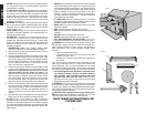
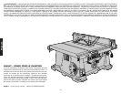
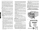
CAUTION: Failure to securely mount the table saw to the
work surface can be hazardous.
1. Center the saw on a square piece of 1/2" (12.7mm) ply-
wood. The plywood must have a 15" by 20" opening to
allow dust to escape.
2. Mark the positions of the four mounting holes in the base
of the saw with a pencil.
3. Remove the saw and drill 1/4" (6.4mm) holes in the
places you have just marked.
4. Position the saw over the four holes you drilled in the
plywood and insert four 1/4" (6.4mm) machine screws
FROM THE BOTTOM. Install washers and 1/4" (6.4mm)
nuts on the top. Tighten securely.
5. In order to prevent the screw heads from marring the
surface to which you clamp the saw, attach two strips of
scrap wood to the bottom of the plywood base. These
strips can be attached with glue, or wood screws can be
installed from the top side as long as they don’t protrude
through the bottom of the strip.
6. “C” clamp the plywood base to your workbench when-
ever you want to use the saw.
CAUTION: Make sure table saw is firmly mounted before
use.
Connecting Saw to Power Source
IMPORTANT: Before connecting saw to power source,
make sure the switch is in the OFF position.
Be sure your power supply agrees with the nameplate mark-
ing. AC ONLY means that your saw will operate on alternat-
ing current only. A voltage decrease of 10 percent or more
will cause a loss of power and overheating. All DeWalt tools
are factory tested. If this tool does not operate, check the
power supply.
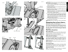
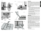
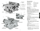
Rip Fence Operation
RAIL LOCK LEVER
The rail lock lever locks the rip fence rails in place, prevent-
ing their movement. To lock the rail lock lever, push it down.
To unlock the lever, pull it up (see Figure 9).
NOTE: When ripping, always lock the rail lock lever.
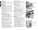
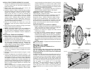
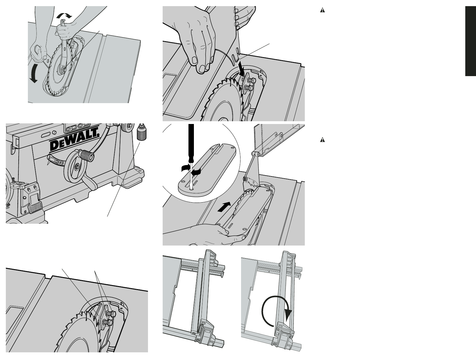
WORK SUPPORT EXTENSION
Your table saw is equipped with a work support extension to
support work that extends beyond the saw table. To use the
work support extension, rotate it as shown in Figure 13.
When not in use, the work support extension retracts, as
shown in Figure 14.
NOTE: Retract the work support extension whenever work-
ing over the table.
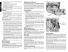
FINE ADJUST KNOB
The fine adjust knob (shown in Figure 15) allows smaller
adjustments when setting the fence. Before adjusting, be
sure the rail lock lever is in its up, or unlocked, position.
RIP SCALE POINTER
NOTE: The rip scale pointer will need to be readjusted
whenever a thicker or thinner blade is installed.
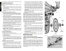
FIG.8
FIG. 10
BOLTS
SHIMS
ARBOR
WRENCH
FIG. 11
FIG. 12
FIG. 13
FIG. 14
EDGE OF
SPLITTER
FIG. 9
RAIL LOCK LEVER