


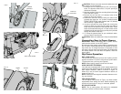
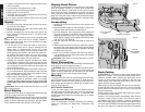
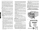
On-Off Switch
Lift the switch paddle up to turn your saw ON and push it
down to turn your saw OFF.
A hole is provided in the switch for insertion of a padlock to
lock the saw off (Figure 17).
WARNING: Be sure switch is in the OFF position before
plugging machine in.
Adjustments
NOTE: Your saw is fully and accurately adjusted at the fac-
tory at the time of manufacture. If readjustment due to ship-
ping and handling or any other reason is required, follow the
steps below to adjust your saw.
Once made, these adjustments should remain accurate.
Take a little time now to follow these directions carefully to
maintain the accuracy of which your saw is capable.
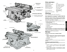
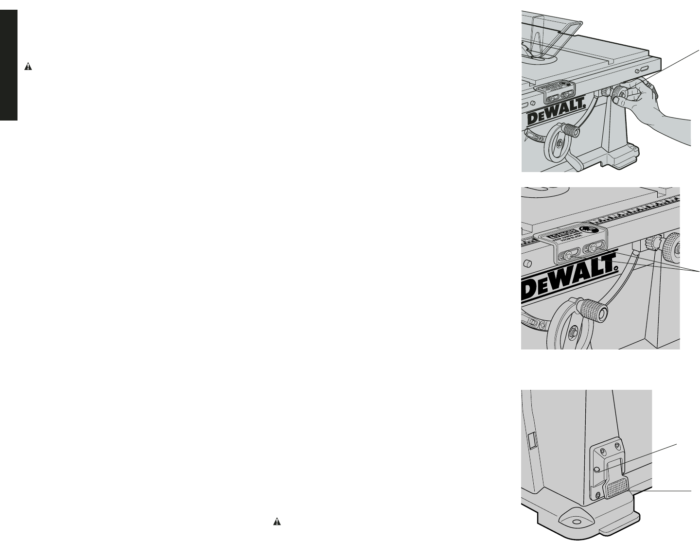
RAIL LOCK ADJUSTMENT
1. Lock the rail lock lever (Figure 9) by pushing down.
2. On the underside of your saw, tighten the nut shown in
Figure 18. Adjust this nut until the gap between the
belleville washers closes.
3. Once the springs are almost touching, tighten the nut
1/2 turn.
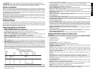
RIP SCALE ADJUSTMENT
See “ADJUSTING THE RIP SCALE” on page 4.
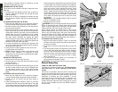
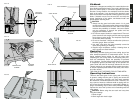
ADJUST BLADE ALIGNMENT TO TABLE
1. THE SAW MUST BE UNPLUGGED BEFORE YOU
MAKE ANY ADJUSTMENT TO THE BLADE.
2. Place the unit in an upright position. Using a 10mm
socket, loosen rear pivot bracket fasteners just enough
to allow the bracket to move side-to-side.(Figure 7A).
3. Adjust the bracket until the blade is parallel to the miter
gauge slot.
4. Tighten the rear pivot bracket fasteners to 7-8 ft.lbs.
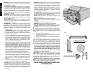
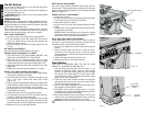
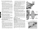
BEVEL STOP AND POINTER ADJUSTMENT
1. Raise the blade fully by rotating the blade height adjust-
ment wheel clockwise until it stops.
2. Unlock the bevel lock lever (Figure 3) by pushing it up
and to the right. Loosen the bevel stop screw
(Figure 19).
3. Place a square flat against the table top and against the
blade between teeth, as shown in Figure 20. Ensure the
bevel lock lever is in its unlocked, or up, position.
4. Using the bevel lock lever, adjust the bevel angle until it
is flat against the square.
5. Tighten the bevel lock lever by pushing it down.
6. Turn the bevel stop cam until it firmly contacts the bear-
ing block. Tighten the bevel stop screw.
7. Check the bevel angle scale. If the pointer does not read
0°, loosen pointer screw (see Figure 19) and move the
pointer so it reads correctly. Retighten the pointer screw.
8. Repeat at 45°, but do not adjust pointer.
MITER GAUGE ADJUSTMENT
Your miter gauge features adjustable stops at 90° and 45°
left and right. To adjust these stops, loosen the lock nuts and
tighten or loosen the three adjusting screws against the stop
plate (see Figure 21).
FENCE PARALLEL ADJUSTMENT
1. Unlock rail lock lever.
2. Locate rear pinion bearing and loosen the two hex bolts
just enough to allow side-to-side movement.
3. Adjust fence parallel to blade.
4. Lock rail lock lever and check parallel alignment of the
blade.
5. Tighten the 2 hex bolts that secure the rear pinion bear-
ing assembly to the table.
NOTE: If there is not enough travel in the pinion bearing
assembly to allow the fence to be parallel to the blade,
take the unit to an authorized service center.
RACK AND PINION MESH ADJUSTMENT
Proper adjustment of the rack and pinion mesh is done at
the factory. If it should become necessary to adjust the rack
and pinion mesh, use the following procedure.
1. Turn the saw upside down and locate the front pinion
bearing.
2. Using a narrow blade screw driver or #20 torx driver,
access the screw through the slot. Loosen the screw
(counterclockwise) until the head touches the inside of
the bearing box.
3. Tighten the screw (clockwise) 3/4 of a turn.
4. Repeat procedure for rear pinion bearing.
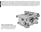
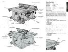
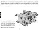
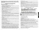
Saw Blades
THIS SAW IS INTENDED FOR THE USE OF SAW
BLADES 10" IN DIAMETER OR SMALLER
1. The saw blade furnished with your new saw is a 10"
(254mm) combination blade, used for cross cutting
(across the grain) and ripping (with the grain) through
the material. The center hole to fit on the arbor is 5/8"
(16mm) diameter (.625"). This blade will produce a good
quality cut for most applications.
2. There are many types of blades available to do specific
and special jobs such as cross cut only, rip only, hollow
ground, thin plywood, paneling, etc.
3. Use only saw blades designed for maximum safe oper-
ating speeds of 5,000 RPM or greater.
4. Saw blades should always be kept sharp. It is recom-
mended that you locate a reputable sharpening service
to sharpen your blades when needed.
5. Never stack blades on top of one another to store. Place
material such as cardboard between them to keep the
blades from coming in contact with one another.
CAUTION: Abrasive wheels should not be used on this
saw.
English
FIG. 15
FIG. 16
ON-OFF
SWITCH
PADLOCK
INSERTION
HOLE
SCREWS
FINE ADJUST KNOB
FIG. 17
6