


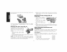
Thesidehandleshouldbeusedasthesecondarygripsurfaceforall
otherapplications.
FIG.3 \
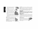
Thegearcasegripmaybepurchasedat additionalcost.Please
call 1-800-4-DEWALT(1-800-433-9258)or visit ourwebsite:
www.dewalt.com.
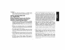
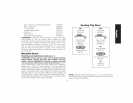
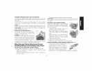
Ro*a*in9 the Gear Case (Fig. 4)
For applications in which a tool will be FIG.4
dedicated for uses in edge grinding and
finishing work, the gear case may be
rotated 90 ° left or right of its original
position.
1. Remove the four corner screws
attaching the gear case to motor
housing.
2. Without separating the gear case from motor housing, rotate the
gear case head to desired position.
NOTE: If the gear case and motor housing become separated
by more than 1/8" (3.17 mm), the tool must be serviced and
re-assembled by a DEiWALTservice center. Failure to have the tool
serviced may cause brush, motor and bearing failure.
10
3. Reinstall screws to attach the gear case to the motor housing.
Tighten screws to 20 in.-Ibs, torque. Overtightening could cause
screws to strip.
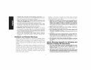
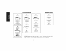
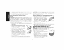
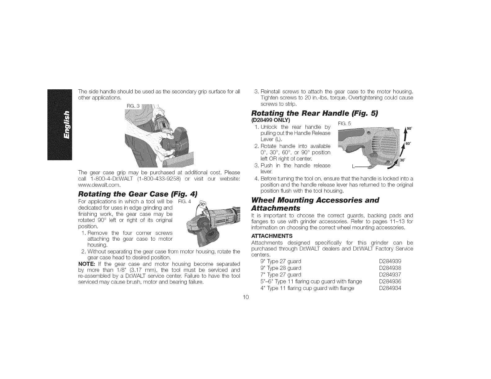
Rotating the Rear Handle (Fig. 5)
(D28499 ONLY} FIG.5
1. Unlock the rear handle by _90o
pulling out the Handle Release
1
Lever (L).
2. Rotate handle into available 6°°
0°, 30°, 60°, or 90° position
left OR right of center.
3. Push in the handle release
lever.
4. Before turning the tool on, ensure that the handle is locked into a
position and the handle release lever has returned to the original
position flush with the tool housing.
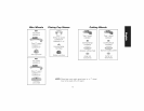
Wheel Mountin9 Accessories and
Attachments
It is important to choose the correct guards, backing pads and
flanges to use with grinder accessories. Refer to pages 11-13 for
information on choosing the correct wheel mounting accessories.
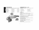
ATTACH MENTS
Attachments designed specifically for this grinder can be
purchased through DEWALT dealers and DEWALT Factory Service
centers.
9" Type 27 guard D284939
9" Type 28 guard D284938
7" Type 27 guard D284937
5"-6" Type 11 flaring cup guard with flange D284936
4" Type 11 flaring cup guard with flange D284934