


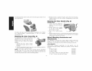
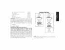
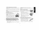

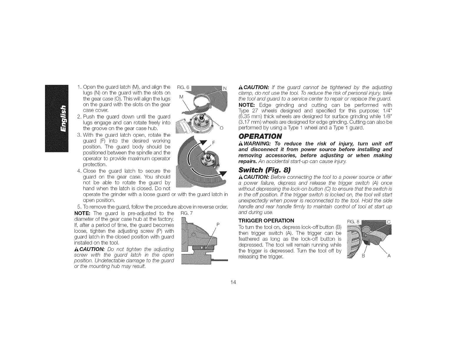
1.Opentheguardlatch(M),andalignthe FIG.6 N
lugs(N)ontheguardwiththeslotson
thegearcase(O).Thiswillalignthelugs M
ontheguardwiththeslotsonthegear
casecover.
2.Pushtheguarddownuntiltheguard
lugsengageandcanrotatefreelyinto
thegrooveonthegearcasehub. O
3.Withtheguardlatchopen,rotatethe
guard(F)into thedesiredworking F
position.Theguardbodyshouldbe
positionedbetweenthespindleandthe
operatortoprovidemaximumoperator
protection.
4.Closetheguardlatchto securethe
guardonthegearcase.Youshould
notbe ableto rotatetheguardby
handwhenthelatchisclosed.Donot
operatethegrinderwithalooseguardorwiththeguardlatchin
openposition.
5.Toremovetheguard,followtheprocedureaboveinreverseorder.
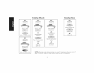
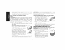
NOTE:Theguardis pre-adjustedto the FIG.7
diameterofthegearcasehubatthefactory.
If,afteraperiodoftime,theguardbecomes P
loose,tightentheadjustingscrew(P)with
guardlatchintheclosedpositionwithguard
installedonthetool.
_ CAUTION: Do not tighten the adjusting
screw with the guard latch in the open
position. Undetectable damage to the guard
or the mounting hub may result.
j_CAUTION: If the guard cannot be tightened by the adjusting
clamp, do not use the tool To reduce the risk of personal injury, take
the tool and guard to a service center to repair or replace the guard.
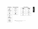
NOTE: Edge grinding and cutting can be performed with
Type 27 wheels designed and specified for this purpose; 1/4"
(6.35 mm) thick wheels are designed for surface grinding while 1/8"
(3.17 mm) wheels are designed for edge grinding. Cutting can also be
performed by using a Type 1wheel and a Type 1 guard.
OPERATION
_WARNING: To reduce the risk of injury, turn unit off
and disconnect ff from power source before installing and
removing accessories, before adjusting or when making
repairs. An accidental start-up can cause injury,
Switch (Fig. 8)
i_ CAUTION: Before connecting the tool to a power source or after
a power failure, depress and release the trigger switch (A) once
without depressing the lock-on button (C) to ensure that the switch is
in the off position. If the trigger switch is locked on, the tool will start
unexpectedly when power is reconnected to the tool Hold the side
handle and rear handle firmly to maintain control of tool at start up
and during use.
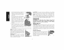
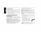
TRIGGER OPERATION FIG.8
To turn the tool on, depress lock-off button (B)
then trigger switch (A). The trigger can be
feathered as long as the lock-off button is
depressed. The tool will remain running while
the trigger is depressed. Turn the tool off by
releasing the trigger. B A
14