


10
OPERATING CONTROLS AND ADJUSTMENTS
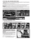
Fig. 12
Fig. 13
Fig. 15
B
A
B
C
B
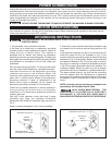
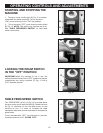
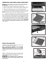
STARTING AND STOPPING THE
MACHINE
1. The drum motor on/off switch (A) Fig. 12 is located
underneath the switch shield (B). To turn the drum
“ON”, move switch (A) to the “ON” (up) position.
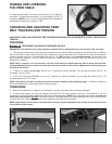
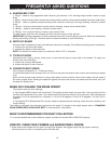
2. To turn the drum “OFF”, push down on switch shield
(B) Fig. 13. NOTE: This switch only controls the drum.
See “TABLE FEED/SPEED SWITCH” for feed table
switch instructions.
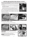
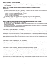
LOCKING THE DRUM SWITCH
IN THE “OFF” POSITION
IMPORTANT: When the machine is not in use, the
switch should be locked in the “OFF” position to prevent
unauthorized use, using a padlock (C) Fig. 14 with a
3/16" diameter shackle.
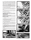
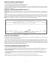
TABLE FEED/SPEED SWITCH
The “FEED/SPEED” switch, (A) Fig. 15 is located above
the drum motor on/off switch shield (B). Rotate the knob
(A) Fig. 15 clockwise to turn the table motor on and
continue to turn it in order to increase the table
feed/speed rates and counter-clockwise to decrease the
speed rates.
To turn the feed table "OFF", turn the knob in a counter-
clockwise direction until it CLICKS "OFF".
Fig. 14
A
D