


9
Fig. 7
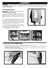
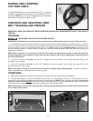
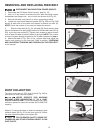
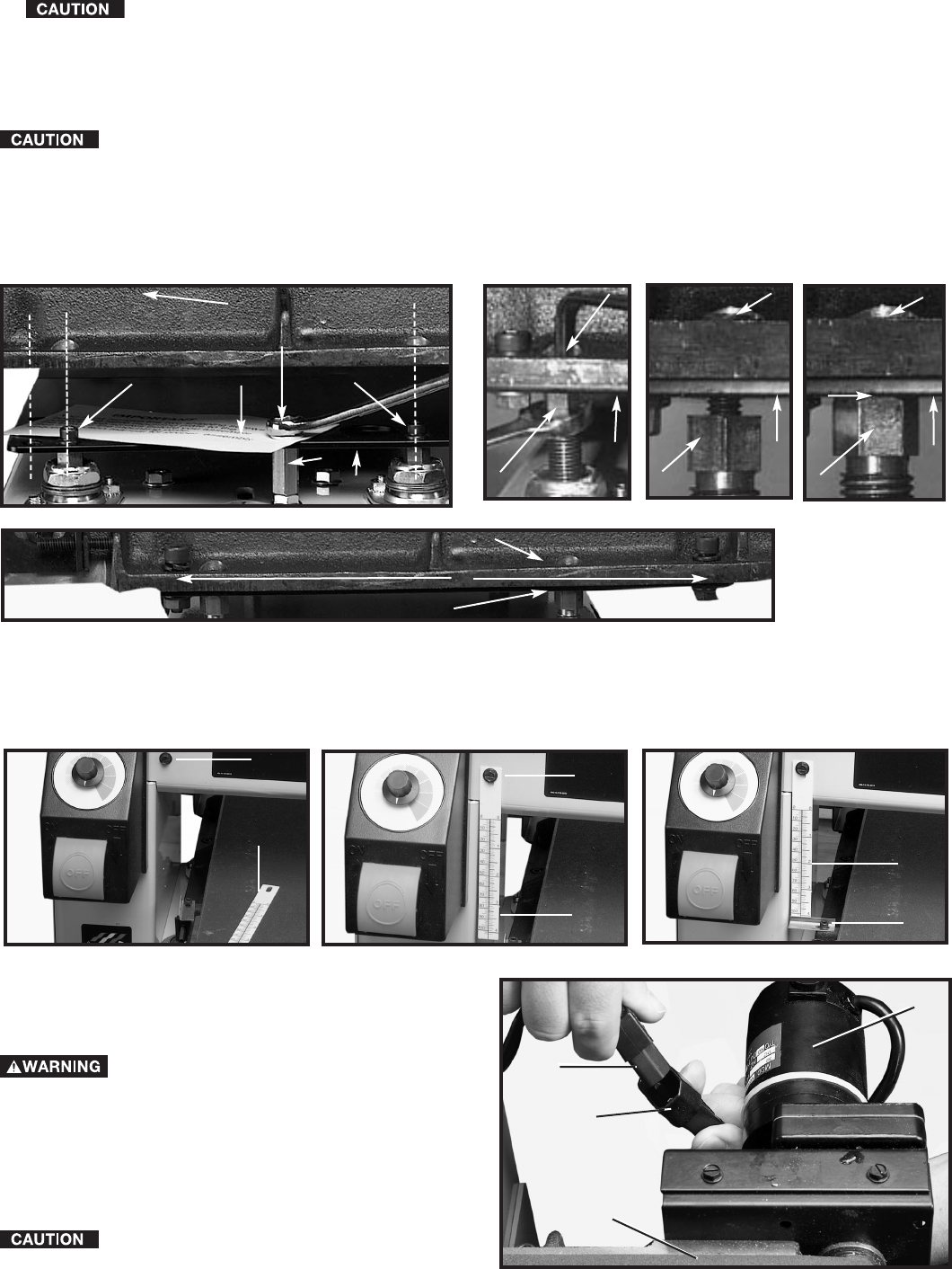
ATTACHING THICKNESS SCALE
1. Remove screw and washer (A) Fig. 7.
2. Place thickness scale (B) Fig. 8 over the hole and replace screw and washer (A).
3. Loosen screw (C) Fig. 9, and position pointer against scale (B) Fig. 9. Tighten screw (C) Fig. 9.
IMPORTANT: Refer to section “CHECKING AND ADJUSTING TABLE HEIGHT” in this manual for adjusting scale.
Fig. 8 Fig. 9
A
B
B
A
C
B
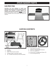
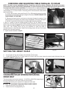
CONNECTING FEED MOTOR TO
FEED/SPEED SWITCH ASSEMBLY
The table feed motor (A) Fig. 10 is
located on the side of the feed table (B). Before
connecting the feed motor to the feed-speed switch
disconnect machine from power source.
1. Insert the feed/speed switch assembly connector
(C) Fig. 10 into the motor connector (D) . Connector is
polarized and will fit only one way.
To avoid damage DO NOT connect the
motor to any other power source.
Fig. 10
D
C
A
B
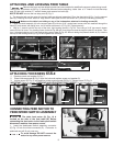
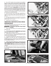
1. Remove the front and rear shipping bolts that were installed to stabilize the support plate during transit.
These bolts, one shown at (N) Fig. 5, should be removed before attaching table. Use a ½" wrench to hold hex stop
post (S) then with another ½" wrench loosen and remove hex bolts (N)
NOTE: DO NOT remove the hex stop post (S) Fig. 5.
2. The abrasive belt and the motor for the feed table are shipped assembled. Place the feed table (A) Fig. 5 on the support
plate (P), inserting the motor side first. Align holes in table (two of which are shown at C) with top of leveling screws (B).
Make sure the table is not sitting on any of the lockwashers attached to leveling screws (B).
3. Fasten the table assembly (A) to the support plate (P) with four 5/16" socket head screws with lock washers through the
holes (D), and secure with flange nuts, two of which are shown in (F) Fig. 6D. Tighten securely.
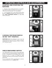
4. With a
½" wrench hold the hex top of the front, right leveling screw (L) Fig .6A. Then using a 3/16" hex wrench loosen
screw (B) four full turns. Turn leveling screw clockwise Fig. 6B until it no longer touches the support plate (P) as shown. Then
turn it counterclockwise until it just touches the support plate (P) Fig. 6C without raising the plate as shown at (O). Hold the
hex top of the leveling screw (L) Fig. 6A and tighten hex screw (B).
Fig. 6B
ATTACHING AND LEVELING FEED TABLE
B
L
Fig. 5
A
B
C
D
C
B
P
S
N
CAUTION:
TAG
Fig. 6C
L
B
P
A
F
Fig. 6D
P
P
Fig. 6A
B
L
P
O