


8
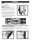
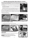
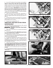
ATTACHING LEGS
This machine is heavy. Use two or more
people when lifting.
1. With the machine on its back, resting on the two
wood blocks (not supplied), attach the legs. (Fig. 1).
NOTE: The legs are universal but the mounting hole
pattern is different front to rear. See (A) Fig. 2A and Fig.
2B.
2. Attach the leg that goes under the motor first. Insert
six carriage head screws through the machine and the
leg and secure with flange nuts (A) Fig. 2A. Attach the
other leg to the machine using the remaining six carriage
head screws and hex nuts. Tighten securely.
4. A cable tie is supplied with the machine to keep the
power cord inside the leg assembly. Secure the power
cord with the cable tie through hole (A) Fig. 2C.
5. CAREFULLY lift the machine upright.
Fig. 1
Fig. 2A Fig. 2B
A
A
Fig. 2C
A
B
A
C
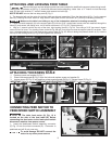
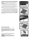
1. Place handwheel (A) Fig. 3, on shaft (B) and align set screw with drilled recess in shaft.
2. Fasten the handwheel to the shaft by tightening the set screw (C) Fig. 4. Make sure set screw contacts the drilled recess
in the shaft and not the O.D. of the shaft.
3. The machine is shipped with the support plate lowered to the bottom. Turn the handwheel counterclockwise two
turns to raise the support plate off the bottom stops.
Fig. 4
Fig. 3
ATTACHING THE HANDWHEEL
ASSEMBLY
FOR YOUR OWN SAFETY, DO NOT CONNECT THE MACHINE TO THE POWER SOURCE UNTIL
THE MACHINE IS COMPLETELY ASSEMBLED AND YOU READ AND UNDERSTAND THE ENTIRE
INSTRUCTION MANUAL.