


14
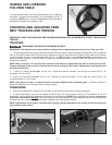
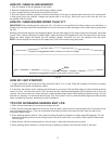
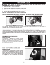
DUST COLLECTION
The drum cover has a 4” O.D. dust chute (A) Fig. 35 that
connects to a dust collection system.
NEVER OPERATE THIS MACHINE
WITHOUT FIRST CONNECTING IT TO A DUST
COLLECTION SYSTEM. It is recommended that a dust
collection system be used with at least 400 to 600 CFM
capacity.
Attach a 4" hose to the hood, or attach an accessory dust
collector elbow (B) Fig. 35 to the dust chute (A). Attach
the dust collection system to the elbow (B).
FOR OPERATOR SAFETY, NEVER PUT
FINGERS OR ANY OTHER FOREIGN OBJECT IN THE
DUST CHUTE.
Fig. 33A
Fig. 34
A
B
Fig. 32
A
Fig. 35
B
A
A
D
B
D
E
F
Fig. 33B
D
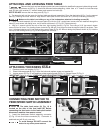
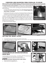
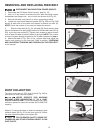
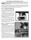
REMOVING AND REPLACING FEED BELT
DISCONNECT MACHINE FROM POWER SOURCE.
1. Disconnect the DC Motor Quick Connect. (see Fig. 10).
2. Use a 1/4" hex wrench to remove the four table mounting screws,
lockwashers and flange nuts , two of which are shown at (A) Fig. 32.
3. Remove the table, and place it on a firm supporting surface.
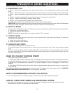
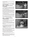
4. Loosen the two socket head set screws (D) Fig. 33A and Fig. 33B
equally at each side of the table until tension is relieved on roller (E).
NOTE: Count the number of turns as you loosen the screws.
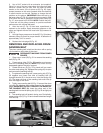
5. Slide the feed belt (A) Fig. 34, off table (B). Place the new feed
belt on the table and re-apply slight tension to the feed belt roller (E) Fig.
33A, by turning two screws (D). Tighten both screws an equal amount
until at least one side of the belt starts to get tight. NOTE: The number
of turns to tighten should be less than the number loosened in step 4.
6. Attach the table (F) Fig. 33A, to the support plate and adjust the
tension and tracking on the feed belt. Refer to section “CHECKING
AND ADJUSTING TRACKING AND TENSION ON THE FEED BELT”
in this manual.