


4E7F
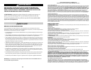
FILLING THE SPRAYER
Make sure the filter basket is in place to keep debris from entering the tank.
Determine the amount of mixture needed for your application. Add the proper amount of water to the
tank. Add the proper amount of chemical to the tank (check the chemical label for proper ratio of
chemical). Stir mixture in tank with a clean utensil (like a paint stirrer). The tank will hold the 4-gallon
(15.1L) capacity plus the chemical.
It is not necessary to completely fill the sprayer tank with each use. You can fill the tank with only the
amount needed for each application.
Always follow the manufacturer’s instructions included on their product label.
Stage 4
(Removable
Shut-off filter)
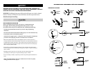
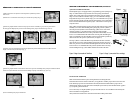
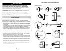
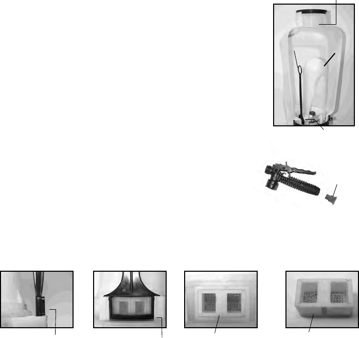
4 STAGE FILTERING SYSTEM
This backpack sprayer is equipped with a 4 stage filtering system (see figure 1).
Stage 1 is a filter basket incorporated into the tank opening where fluid is
added. Stage 2 and 3 filters are located at the inlet of the pressure cylinder.
Stage 2 is a removable In-Tank filter. Stage 3 is a removable filter cartridge
integrated into the pressure cylinder. Stage 4 is a removable filter incorporated
into the shut-off assembly. Periodic cleaning of these filters is recommended to
insure consistent fluid flow through the sprayer. This will also reduce sprayer
component wear.
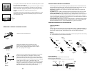
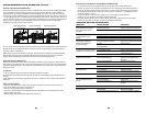
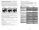
Stage 3 filter cartridge cleaning requires removal of the entire pressure cylinder
assembly (see section “disassembling and repairing the pressure cylinder”).
Once the pressure cylinder is removed the stage 3 filter can be removed for
cleaning (see figure 3). Periodic cleaning of the stage 2 filter is highly
recommended and will reduce the need to perform this disassembly. It is best
to have no or minimal fluid in the tank before removing and reinstalling the
stage 2 In-Tank filter. The In-Tank filter needs to be oriented in a specific way
when inserted into the pressure cylinder base (see figure 2).
The stage 4 filter is a removable filter incorporated into the inlet side of the
shut-off valve (see section “disassembling and repairing the shut-off valve”) .
Make sure pressure is released before detaching the hose from the shut-off. It
is best to have no or minimal fluid in the pressure cylinder before removing
and reinstalling the stage 4 shut-off filter as fluid can leak from the hose.
Stage 1
(filter
basket)
Stage 2
(removable
In-Tank filter)
Figure 1
Stage 3 (removable
filter cartridge)
Figure 2 Stage 2 (removable In-Tank filter)
Figure 3 Stage 3 (removable filter cartridge)
Filter cartridge removedFilter cartridge in
pressure cylinder base
Guide edge facing away
from pressure cylinder
Guide edge on
pressure cylinder
Pressure
Cylinder
SPRAYER COMPONENTS & USE INFORMATION, Continued
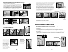
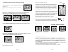
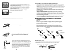
1) Retirez la pression du cylindre et tout le liquide du cylindre de pression
et de la cuve.
2) Retirez les 2 vis rattachant le levier du pivot à l'arbre de la pompe (Fig. 1).
3) Retirez la goupille fendue de l'arbre de la pompe et retirez la rondelle (Fig. 2a). Tirez et glissez l'arbre
du côté opposé le déplaçant du parcours de l'assemblage de la pompe à membrane (Fig. 2b et 2c).
4) Dévissez la pompe à membrane de la base du cylindre de pression. Il faudra peut-être utiliser une clé à
sangle ou un autre moyen mécanique (Fig. 3).
6) Jetez l'assemblage de pompe à membrane.
DÉMONTER ET REMPLACER LA POMPE À MEMBRANE
5) Retirez la goupille fendue de la connexion du levier du pivot de l'assemblage de la pompe à membrane. Retirez
le levier et la quincaillerie de connexion de l'assemblage de pompe à membrane (Fig. 4b et 4c).
Figure 1
Figure 2a
Figure 4a
Figure 2b
Figure 2c
Figure 4b
Figure 3
Connexion de
levier du pivot