In-tank Filter
8E
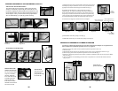
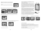
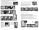
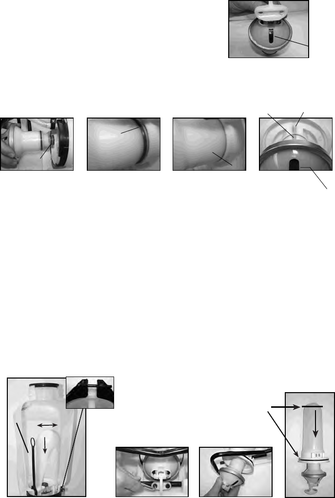
8) Apply Petroleum jelly to 2 diaphragm pump o-rings (Fig. 6a).
Thread diaphragm pump assembly into pressure chamber base,
making sure the o-ring seats inside the pressure chamber base
(Fig. 6b-6c). Align the diaphragm pump alignment mark with the
pressure cylinder base alignment mark (fig.6d).
The slot in the diaphragm cover will also be in alignment.
9) Re-assemble pump shaft (see step 3).
10) Re-attach pivot lever to pump shaft (see step 2).
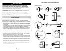
Only remove the pressure cylinder if the cartridge filter is clogged or the sprayer is
leaking fr
om where the pressure cylinder o-ring and tank meet.
DISASSEMBLING AND REPAIRING THE PUMP ASSEMBLY
7) Attach pivot lever and connection hardware to new diaphragm pump
assembly. Make sure orientation is correct with slot in diaphragm cover
( Fig. 5).
Figure 5
Figure 6d
Pressure Cylinder Base
Alignment Mark
Diaphragm Pump
Alignment Mark
Diaphragm
Cover Slot
Figure 6c
Pressure
Cylinder Base
Figure 6b
O-ring
Figure 6a
O-rings
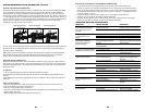
1. Release the pressure from the sprayer and remove all liquid from both the pressure cylinder and tank.
2. Remove Hose
3. Remove the In-tank Filter from the pressure cylinder (located inside tank fig 1).
4. Remove the large clamp holding the pressure cylinder and tank together (fig 1).
5. Rock the pressure cylinder back and forth and push down forcefully to free it from the tank (fig 1).
6. Once freed the entire assembly can be removed by angling and maneuvering it through the base frame
(fig 3a & 3b).
Figure 2
Figure 3a Figure 3b
Pressure
Cylinder o-ring
Diaphragm
Cover Slot
Clamp
Figure 1
3F
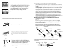
INFORMATION D'UTILISATION ET COMPOSANTS DU PULVÉRISATEUR, suite
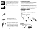
INSTALLER LA POIGNÉE DE POMPE
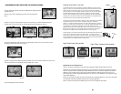
La poignée de pompe s'installe à l'une ou l'autre extrémité de l'arbre
de la pompe (A). Pour installer la poignée de pompe, placez la
poignée (C) sur l'arbre (A) en alignant le trou de la poignée de pompe
et le trou de l'arbre. Poussez le côté droit de la goupille fendue (B) à
travers le trou aligné tel qu'indiqué dans les figures 1 à 3. Il y a dans
trous dans la poignée de la pompe pour permettre un montage de
gaucher (fig. 4) ou droitier (fig. 5).
INSTALLER LA
BANDOULIÈRE
Le dessus des
bandoulières est fixé à
la cuve. Fixez
l'extrémité inférieure
des bandoulières en
attachant les crochets
de sangle à l'armature
de métal entre l'endroit
où celle-ci sort de la
cuve et où elle se
recourbe.
PINCE DU TUBE
Le tube s'installe à
la poignée de la
pompe en utilisant
la pince du tube.
A
C
B
Relevez
Tournez
de 180º
Placez
dans
la
fente
Pump Handle
Positioned For Use
(right hand shown)
Figure 5
Droitier
Figure 4
Gaucher
POIGNÉE DE POMPE ESCAMOTABLE
Figure 1
Goupille fendue
Figure 2
Alignez les trous
Figure 3
Glissez la goupille à travers les trous.


