


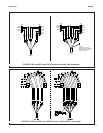
MODEL 228 USE OF INSERTION - RETRACTION ASSEMBLIES
1. Retract the sensor into the retraction chamber and
fully close the ball valve.
2. Drain the retraction chamber contents using the
1/8 in. flush ports.
3. (Mechanical) Mark the location of the nut housing
cap and retraction collar on the sensor tube.
Remove both socket head cup screws from the nut
housing and loosen the retraction stop collar.
4. Remove the 3 in. Hex Union nut.
5. Withdraw the sensor from the retraction chamber.
6. Open the junction box and disconnect the sensor
wires from the terminal block.
7. Remove the compression fitting just below the
junction box and remove the junction box from the
sensor tube.
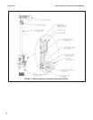
8. (Manual) Pull down the nut guard and remove the
collet nut from the bushing housing.
9. Slide all hardware including the bushing housing
off the sensor tube.
10. Remove the retaining ring from the bottom of the
bushing housing.
11. Remove the Teflon guard.
12. From the top of the bushing housing press out the
Teflon bushing. This will also push out the Teflon
cup seal.
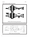
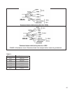
13. Replace all damaged parts with replacement parts
from Figure 16 or 17. Replace the sensor tube if
the surface is damaged. A rough or uneven surface
will prevent the Teflon cup from sealing.
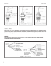
14. Rebuild the bushing housing. The open end of the
cup seal (spring visible) faces the process.
15. Carefully slide the bushing housing onto the sen-
sor tube. Do not damage the Teflon bushing or the
Teflon cup seal.
16. (Manual) Slide the 3 in. Hex Union nut, collet nut
with nut guard, junction box compression nut, and
plastic ferrules onto the sensor tube.
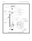
17. (Mechanical) Slide the 3 in. Hex Union nut, retrac-
tion stop collar, junction box compression nut, and
plastic ferrules onto the sensor tube.
18. Connect the junction box to the sensor tube and
wire the sensor leads to the appropriate terminals.
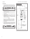
19. (Mechanical) Lock the retraction stop collar into
position (see Figure 15 or previously marked posi-
tion for proper location).
20. Place the Union nut O-ring on the bottom of the
bushing housing. Insert the sensor assembly into
the retraction chamber and tighten the 3 in. Hex
Union nut.
21. (Mechanical) Install the nut housing cap (see
Figure 15 or previously marked position for proper
location).
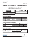
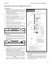
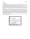
REPLACING SEALS IN MANUAL AND MECHANICAL RETRACTION ASSEMBLIES.
WARNING
Retraction chamber contents may be under pressure.
10