


7
MODEL 228 USE OF INSERTION - RETRACTION ASSEMBLIES
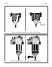
INSERTION - RETRACTION ASSEMBLIES
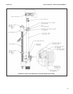
MANUAL RETRACTION ASSEMBLY (PN 23311-01)
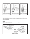
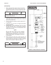
INSTALLATION
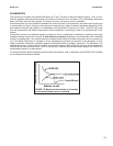
1. Loosen the collet nut and retract the sensor tube into the retraction chamber. See Figure 14.
2. Loosen the union nut and separate the retraction chamber from the assembly.
3. Install the retraction chamber on the 1-1/2 in. NPT full port ball valve mounted on the process line or vessel.
4. Thread the sensor cable through the tube into the junction box. Screw the sensor into the tube. Hand tighten
the sensor an additional half turn once the gasket is seated.
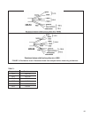
5. Connect the sensor and interconnecting cable leads to the terminal strip in the junction box. See figure 13.
6. Connect the other end of the cable to the analyzer. See the wiring diagrams in Figures 5 through 10. For cable
PN 23294-00 follow the wiring for the 228-54 sensor. For cable PN 23294-04 and 23294-05, follow the wiring
for the 228-56 sensor, with the following exception:
Refer to the wire function diagram for the 228-56 option in figure 4 and identify the RTD wire
bundle. Connect the RTD wires to the analyzer as follows:
Green – RTD in
Black – no connection
Clear – RTD common or RTD return
White – RTD sense
Wrap the bare end of the black wire to prevent accidental connections.
7. Insert the sensor and tube assembly into the retraction chamber.
8. Tighten the union nut.
9. Open the ball valve, check for leaks, and manually insert the sensor into the process.
10. Position the sensor at least 1/2 in. (13 mm) away from any wall of the vessel or pipe.
11. Tighten the collet nut.
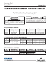
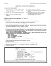
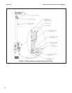
INSTALLATION REQUIREMENTS
1. Process connection: 1-1/2 inch. Larger openings
may keep the sensor from inserting far enough
into the process liquid.
2. Line size: 3 in.; 2-in. line requires in-place calibra-
tion.
3. Valve: 1-1/2 NPT full port ball valve (PN
9340065).
4. Retraction clearance: 2 ft (0.6 m).
5. Provide mechanical support if excess vibration is
expected.
6. Flush water: provide 1/8 in. valves in inlet and
outlet flush ports. Position flush ports so that
retraction chamber can be drained.
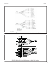
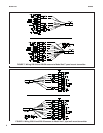
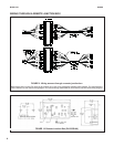
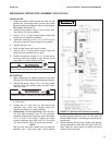
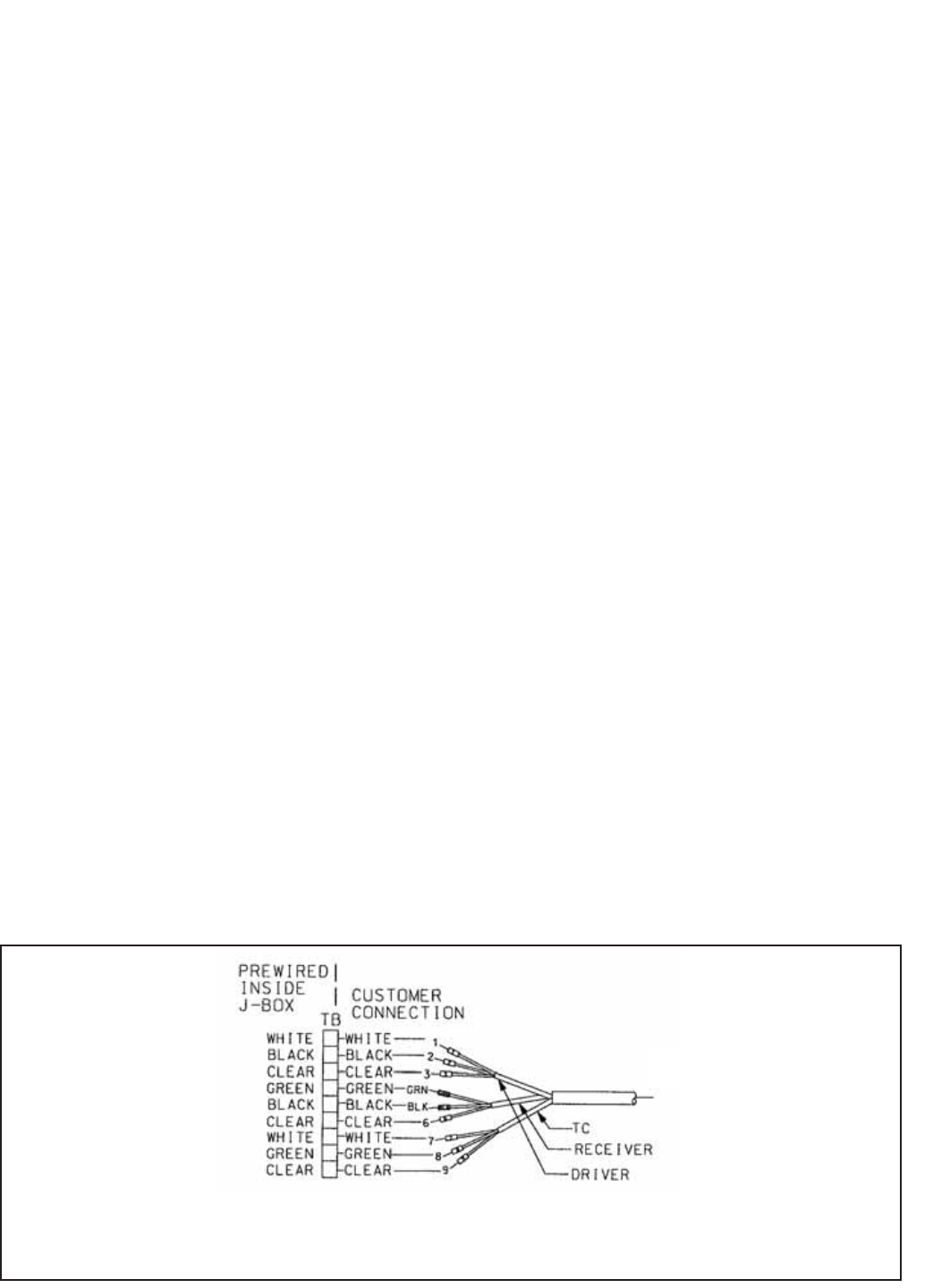
FIGURE 13. Sensor-Mounted Junction Box Wiring
Note: Interconnecting cables PN 23924-04 and 23294-05 have four RTD (TC) leads: clear, black, white, and green. Do not
connect the black RTD (TC) lead. Cable PN 23294-05 has a clear outer shield. See Figure 11. Do not connect the outer shield.
23294-00
(For cables 23294-04 and
23294-05, see note)