


8 2008SSD-34 (5/08)
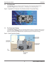
Single-Compressor Module Installation
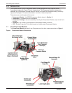
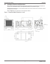
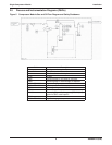
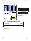
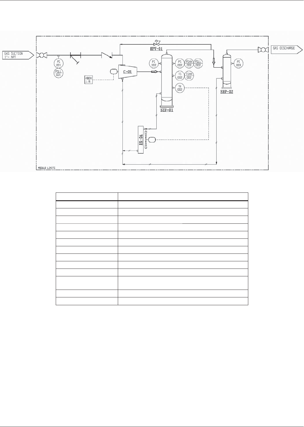
2.5 Process and Instrumentation Diagrams (P&IDs)
Figure 5 Compressor Module Gas and Oil Flow Diagram and Safety Shutdowns
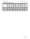
Code Description
BPV-01 Gas bypass valve (optional)
C-01 / C-02 Compressor and motor
EX-04 Oil cooler, fan controlled by thermistor
FL-05 Oil fi lter
PI002 Pressure gauge on fi rst-stage oil separator
PI003 Pressure gauge on second-stage oil separator
PS002 / PSHH002 High discharge gas pressure switch
PS001 / PSLL001 Inlet low pressure switch
SEP-01 First-stage oil separator, 6” O.D.
SEP-02 Second-stage oil separator/coalescing element
TCV-03 Thermal bypass valve, 3-way, set @ 200°F (93°C)
option for 250F, model specifi c
TE002 Fan speed thermistor
TS002 / TSHH002 High discharge gas temp switch