


Dual-Compressor Module TABLE OF CONTENTS
iii 2008SSD-34 (5/08)
FIGURES
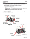
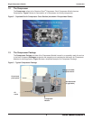
Figure 1 Compressor Module Components ........................................................................................................3
Figure 2 Copeland Scroll
®
Compressor Cross Section ........................................................................................4
Figure 3 Typical Compressor Package ...............................................................................................................4
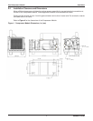
Figure 4 Compressor Module Dimensions, in. (mm) ............................................................................................7
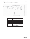
Figure 5 Compressor Module Gas and Oil Flow Diagram and Safety Shutdowns ..............................................8
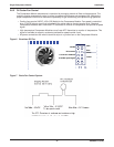
Figure 6 Brushless DC Fan ...............................................................................................................................10
Figure 7 Basic Fan Control System ..................................................................................................................10
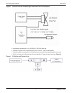
Figure 8 Optional Customer-Installed High Temperature Fan Control System .................................................11
Figure 9 Oil Cooling and Thermal Valve ............................................................................................................. 11
Figure 10 Motor Control ......................................................................................................................................12
Figure 11 Typical Compressor Module Electrical Requirements .........................................................................13
Figure 12 Control Circuit Terminations ................................................................................................................14
Figure 13 Power Terminations .............................................................................................................................14
Figure 14 30 HP VFD Connections ......................................................................................................................15
Figure 15 Maintenance Tools ...............................................................................................................................20
Figure 16 Adding or Draining Oil .........................................................................................................................23
Figure 17 Gas Inlet Block and Screen ................................................................................................................25
Figure 18 Scavenge Line Orifi ce .........................................................................................................................25
Figure 19 Oil Filter Bowl and Element ..................................................................................................................26
TABLES
Table 1 Inlet and discharge pressure limits ........................................................................................................5
Table 2 Typical Compressor Module power supply requirements ....................................................................13
Table 3 Default and optional VFD confi gurations .............................................................................................16
Table 4 Typical 30 HP VFD parameters ............................................................................................................16
Table 5 Maintenance summary .........................................................................................................................19
Table 6 Troubleshooting ...................................................................................................................................27
Table 7 VFD fault codes and descriptions ........................................................................................................27
Table 8 Motor winding resistance .....................................................................................................................27
Table 9 Platform troubleshooting guidelines .....................................................................................................28
Table 10 Compressor Module specifi cations ......................................................................................................29
Table 11 Compressor Module fl ow, pressure and horsepower data (see Notes 1 - 4*) .....................................31
Table 12 Contact information ..............................................................................................................................34