


9 2008SSD-34 (5/08)
Dual-Compressor Module Installation
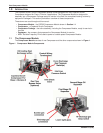
2.6 Electrical Controls
2.6.1 General Considerations
All shutdown devices are dry contact switches rated Class I, Division II that are wired to a terminal box
for connection to the packager supplied control circuit. The common wires on all switches are connected
together. All switches are closed unless a fault condition is detected.
All safety and protective devices must be installed and used in accordance with applicable codes and
regulations.
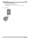
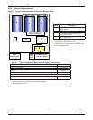
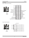
Switches
All switch connections are wired to terminal strips in a junction box on the Compressor Module.
Switch Status
• Low Inlet Gas Pressure Normally Open, closes on pressure rise
• High Discharge Gas Pressure Normally Closed, opens on pressure rise
• High Temperature Normally Closed, opens on temperature rise
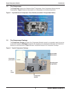
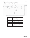
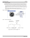
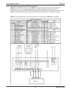
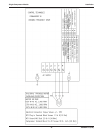
Electrical Considerations - Variable Speed Compressor Module
• Compressor power for a variable speed Compressor Module is the Variable Frequency Drive (VFD).
• Compressor speed control can be either a 4-20 mA or 0-10V signal (transducer supplied by customer)
applied to the VFD. Speed can also be manually controlled with a potentiometer or the VFD can be
set for a fi xed speed.
• The Compressor is protected by the VFD.
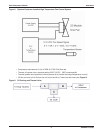
• The customer control circuit must supply an Enable signal to the VFD before the drive will accept a
Run Fwd signal.
• The VFD will start when the Enable signal is on and a Run Fwd signal is applied.
• The VFD will stop if the Run Fwd signal is off or the Enable signal is removed.
NOTE
The drive provides 24V for the Enable and Run Fwd signals.
The installer must connect the Enable and Run Forward terminals to the drive’s 24V terminal.