


18 2008SSD-34 (5/08)
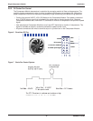
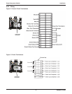
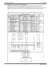
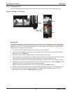
Single-Compressor Module Operation
MAIN POWER
Check for the following conditions:
___ 1. Motor type is correct for the application,
either Variable Speed C3A or C2A motor.
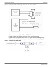
___ 2. Power phasing to the terminal strip and
Compressors is correct.
___ 3. Supply voltage to the Variable Frequency
Drive (VFD) or Fixed Speed Compressor
motors is correct.
___ 4. All chassis, earth grounds are connected.
___ 5. A load reactor or other approved fi lter is
installed for systems with power lead lengths
in excess of 200 ft. (61m) between the VFD
and Compressor Module terminal box.
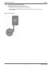
LOW VOLTAGE DEVICES
Verify these conditions for low voltage devices:
___ 1. DC polarity is correct.
___ 2. Temperature control device—if other than
standard thermistor control—is working
properly.
SAFETY AND CONTROL DEVICES
Make sure that all safety and control switches
and devices are confi gured to inhibit Compressor
operation if a fault condition is detected, including:
___ 1. Low inlet pressure switch
___ 2. High discharge pressure switch
___ 3. High temperature switch
___ 4. Variable Frequency Drive (VFD) fault
___ 5. Motor overload trip
___ 6. Other safety and control switches and
devices
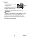
MECHANICAL SYSTEMS
Inspect for these conditions:
___ 1. (Required) Compressor inlet is protected
from water slugging.
___ 2. (Recommended) Gas fi ltration and
treatment is appropriate for the
application.
___ 3. Packager confi guration applies back
pressure to the Compressors.
___ 4. Inlet and discharge valves allow the
module to be isolated.
___ 5. All guards and protective covers are
installed.
___ 6. Protection from freezing is provided if
needed for the application and location.
___ 7. A suitable enclosure providing protection
from the elements is appropriate for the
application and location.
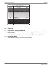
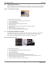
3.1.2 Post-Startup Checklist
Perform these checks AFTER starting the Compressor Module:
DURING INITIAL OPERATION, PERFORM THESE CHECKS:
___ 1. Compressor Module builds pressure on initial startup; no unusual mechanical noise.
___ 2. Oil level is correct at minimum and maximum speeds.
___ 3. No gas leaks are present.
___ 4. No oil leaks are present.
___ 5. Oil cooler fan turn on and run at the appropriate temperature.
___ 6. Oil cooler fan speed varies with temperature.
___ 7. Compressor motor speed varies appropriately for the Packager confi guration.
___ 8. Compressor continues to operate in bypass when the Compressor Module discharge is blocked.
___ 9. Compressor Module is leak tight (maintains approximately 30 psig or more when the Compressors are initially
turned off).
3.2 Initial Startup - Compressor Package
Refer to your Packager’s user manual for information on procedures to start up the Compressor Package,
which includes equipment added to the Compressor Module by the Packager.
3.3 Normal Operation Checklist
Observe the following conditions after startup—when power is applied to the VFD and the VFD receives
the signal from the Compressor Package control system to run: