5 – 7
VSG/VSSG • Installation, Operation and Maintenance Manual •Vilter/Emerson • 35391SSG
Section 5 • Maintenance/Service
1. If equipped with dual oil fi lters, open inlet shut-off
valve for non-operating oil fi lter to put it into opera-
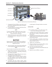
tion, see Figure 5-5.
2. To isolate oil fi lter for servicing, close inlet and out-
let shut-off valves for the oil fi lter.
NOTE
To reduce unwanted oil splash from a vent or drain
valve, connect a hose to the valve port and direct
the gas and oil into a drain pan.
3. Slowly release pressure in the oil fi lter canister by
opening the vent valve. Allow pressures to equalize
to atmosphere.
NOTICE
Dispose of the oil in a appropriate manner following
all Local, State and Federal ordinances regarding the
disposal of used oil.
4. Using an drain pan, open drain valve and allow the
oil to completely drain from the oil fi lter canister.
NOTE
Note orientation of components to aid in installation.
5. Remove bolts and nuts securing cover fl ange to the
oil fi lter canister. Remove cover fl ange and spring
plate. Retain spring plate.
6. If equipped with a single oil fi lter element, remove
fi lter element from oil fi lter canister.
7. If equipped with dual oil fi lter elements, remove
two fi lter elements and fi lter element centering
piece from oil fi lter canister. Retain fi lter element
centering piece.
8. Thoroughly clean the oil fi lter canister, spring
plate and centering piece. Inspect spring plate and
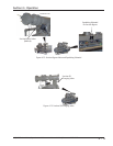
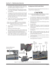
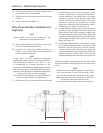
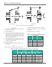
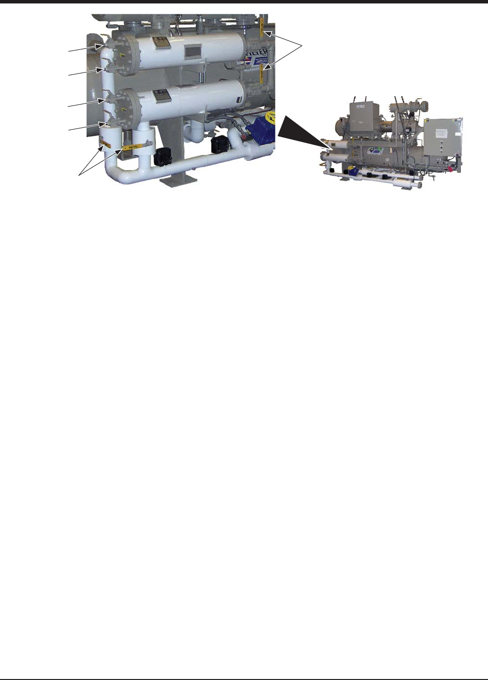
Figure 5-5. Oil Filter Drain, Vent and Shut-Off Valves
Drain Valve
Inlet Shut-Off Valves
Vent Valve
Drain Valve
Vent Valve
Outlet Shut-Off Valves
centering piece, if damaged, replace as required.
INSTALLATION
NOTE
Ensure oil fi lter element on the outlet side is fully
seated on the outlet pipe when installed.
9. If equipped with single oil fi lter element, install oil
fi lter element in canister in orientation noted dur-
ing removal.
10. If equipped with dual oil fi lter elements, install two
oil fi lter elements and centering piece in orientation
noted during removal.
11. Position spring plate in orientation noted during
removal and install bolts and nuts to secure cover
fl ange to oil fi lter canister.
12. Tighten nuts, see Appendix A.
13. Using dry nitrogen gas, pressurize oil fi lter canister
through vent valve and check for leaks.
14. Close the vent valve and drain valve.
15. Open outlet shut-off valve for the oil fi lter that is not
in operation.
16. Repeat for second oil fi lter, as required.


