


4
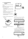
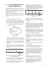
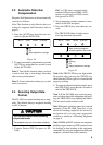
Checking for inclination
Make sure that the PG-1000 is mounted hori-
zontally by the following checks.
1. Press the [TRUE] and [+] keys more than
two seconds.
When the inclination is within ±5°, STATUS
LED lights and TRUE LED blinks.
AUTO TRUE CALIB STATUS
: On
: Blinking
: Off
Figure 8 LED status when
inclination is within
±
5
°
If STATUS LED is off, the inclination is
over ±5°. In this case, relocate the sensor
to where inclination becomes within ±5°
or use a levelling brock.
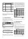
2. Press the [AUTO] and [TRUE] keys more
than two seconds to return to the normal
mode. The STATUS LED blinks while the
sensor is being calibrated and lights when
the calibration is completed (return to nor-
mal mode). Do not operate the equipment
while the LED is blinking; calibration will
be incomplete.
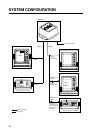
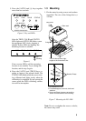
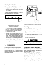
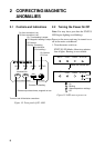
1.4 Connections
Connect cables as shown in the Figure 8.
Leave sufficient slack in cables for mainte-
nance and checking ease. If cables run outside
the bridge run them through conduit to protect
them from corrosion.
-
+
BOW
12-24 VDC
NMEA
AD10
Grounding
12-24 VDC
Ground
terminal
Heading data
External equipment
(Radar, ARPA,
Autopilot, etc.)
Figure 9 Connections of sensor, top view
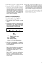
Grounding
Ground the PG-1000 as follows to prevent in-
terference:
• The ground wire should be as short as pos-
sible.
• The ground wire should be about 1.25 sq
and not contain steel.
• Use only a closed end lug.
CAUTION
CAUTION
Ground the equipment
to prevent loss of sensitivity.
Connection of external equipment
IEC-61162-1: Digital interface IEC-61162-1
format input/output terminal. Output: HDG,
HDT, Input: RMC or VTG.
NMEA0183 (Ver.1.5): Outputs HDM (Mag-
netic Heading), HCC (Compass Heading).
AD-10: Outputs heading information in AD-
10 format.
Note: Cover unused connector(s) with the
rubber cap (supplied) to prevent ingress of
water.