


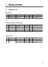

5
1.5 Correcting Magnetic Field
Distortion (Deviation)
The magnetic field at the sensor around ship is
subjects to change with the ship structure,
engins, electronic equipment or any ferrous
materials in the vicinity.
The PG-1000 contains an automatic correction
facility against magnetic field distortion aboard
the ship.
1. Do this procedure in a calm water.
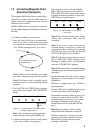
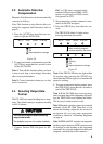
2. Steer the boat clockwise or counterclock-
wise in a circular course. Take more than
two minutes to complete the circle (at about
3 kt). While turning the boat, go to step 3.
2 minutes for a circle
(at about3 kt)
Figure 10
Note 1: Take at least 2 minutes to navigate
the circle, otherwise large error may result.
Note 2: For hover craft or simular vessel,
turn the vessel in a circle maintaining fixed
position.
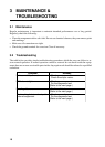
3. Press [AUTO] and [TRUE] keys together
more than two seconds. The CALIB LED
blinks.
AUTO TRUE CALIB STATUS
: Blinking
: Off
Figure 11 Compensatin falt LED status
during compensation
Note: You can return to normal operation
at any time by pressing the [TRUE] key.
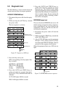
4. Continue turning the boat in a circle (three
to five times) until a result appears.
The correction result is shown with the
LEDs. When correction is successful, all
LEDs light. Wait 30 seconds for the sensor
to return to normal operation, or press the
[TRUE] key for quick return.
AUTO TRUE CALIB STATUS
: On
Figure 12 LED status at successful
correction
Note 1: Do not turn off the power supply
during the correction. Data may be
corrupted.
Note 2: You may restart correction at
anytime during correction or while the
correction results are displayed, by pessing
[AUTO] key. After pressing the key the
AUTO LED lights for two seconds.
Note 3: Continue turning the boat even if
the CALIB LED status changes from
blinking to lighting. Keys are inoperative
when the CALIB LED is lighting.
Note 4: The sensor does not output heading
data during the correction (Program Ver. 3
and after).
5. Anchor the boat at the pier to check sensor
heading to a known point (for example,
lighthouse).
If there is a compass error, see "1.6 Head-
ing Alignment".
If some LED does not light, change sensor
location and repeat step 2 through 4.
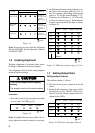
If automatic correction failed at step 4, the
correction result is shown in LEDs. This
continues until you press any key to clear
the display.(Turning off the power at
switch board will not clear the LED dis-
play.)
Note: Bearing output is done with the
status before the automatic correction.
Failure of automatic correction may be
caused by the factors mentioned in the
table below. Try the correction again
referring to the table.