


6
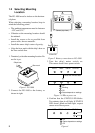
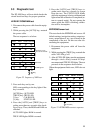
AUTO TRUE CALIB STATUS
: On
: Blinking
Above range of
magnetic sensor
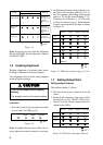
Causes
Results of correction
Remedy
Magnetic field
distortion
Turning error
Follow the
procedure in
above from step
2 after the
replacement of
unit.
Follow the
procedure in
above from step
2 after the
replacement of
unit.
Follow the
procedure in
above from step
2.
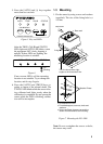
Figure 13
Note: Correction can also be done at Remote
Display DD-2000. See the Operator's Manual
for the DC-2000.
1.6 Heading Alignment
Heading alignment is required when sensor
heading is different from actual heading.
This alignment must be done using magnetic
heading (default setting).
CAUTION
CAUTION
Turn off the autopilot before aligning
heading.
The autopilot may turn the rudder suddenly.
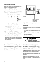
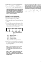
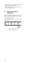
Procedure
1. Press the [-] and [+] keys together more than
two seconds. All LEDs go off.
AUTO
TRUE CALIB STATUS
: Off
Figure 14
Note: Complete the next step within 10 sec-
onds, otherwise normal operation is restored.
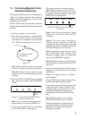
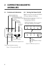
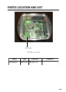
2. Set difference between sensor heading (out-
put) and actual heading with the [+] or [-]
key. For example, the hading output by the
sensor is 70° and the actual heading is 75°.
Therefore, the difference is +5°. Press the
[+] key five times to set +5°. Each time the
[+] key is pressed the LEDs light as shown
in Figure 14.
AUTO
TRUE CALIB
STATUS
: On
: Off
+1°
+2°
+3°
+4°
+5°
+6°
+7°
Repeat
Figure 15 LED state and pressing of [+] key
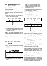
1.7 Setting Output Data
Setting output interval
The deffault setting is 100 ms.
1. Disconnect the power connector from the
sensor.
2. Reattach the connector to the sensor while
pressing the [+] key. The PG-1000 is pow-
ered on, and the current output interval is
shown by the LEDs.
AUTO TRUE CALIB
STATUS
: On
: Off
100ms
200ms
1s
2s
Figure 16 LED state and output interval