


iii
TABLE OF CONTENTS
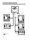
SYSTEM CONFIGURATION .............................................................. iv
SPECIFICATIONS ..........................................................................SP-1
1 INSTALLATION
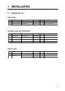
1.1 Equipment List .................................................................................................................... 1
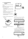
1.2 Selecting Mounting Location .............................................................................................. 2
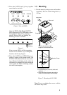
1.3 Mounting ............................................................................................................................. 3
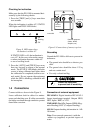
1.4 Connections ......................................................................................................................... 4
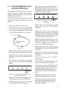
1.5 Correcting Magnetic Field Distortion (Deviation) .............................................................. 5
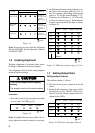
1.6 Heading Alignment ..............................................................................................................6
1.7 Setting Output Data .............................................................................................................6
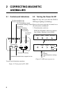
2 CORRECTING MAGNETIC ANOMALIES
2.1 Controls and Indications ...................................................................................................... 8
2.2 Turning the Power On/Off ...................................................................................................8
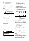
2.3 Automatic Distortion Compensation ................................................................................... 9
2.4 Selecting Output Data Format ............................................................................................. 9
3 MAINTENANCE & TROUBLESHOTTING
3.1 Maintenance....................................................................................................................... 10
3.2 Troubleshooting ................................................................................................................. 10
3.3 Diagnostic Test .................................................................................................................. 11
3.4 Displaying Program Version No. .......................................................................................12
PARTS LOCATION AND LIST ...................................................... AP-1
OUTLINE DRAWING ....................................................................... D-1
SCHMATIC DIAGRAM..................................................................... S-1