


13
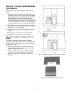
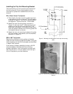
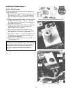
Installing the Phase Sensors
AK-50 & AKS-50 Breakers
Figure 18 shows the parts provided for assembly of
the CT on each pole.
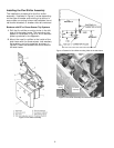
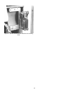
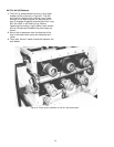
1. Mount the new copper CT post to the back frame
with the two
3
8-16 x 1
1
2" bolts, flat washers,
and lock washers provided, as shown in Figure
19.
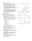
2. Fasten the three small insulated wire fasteners to
the back frame with the
1
4-20 x 1
3
4" screws
provided, as shown in Figure 20. One fastener is
mounted under each CT.
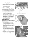
3. Place a CT over each copper post, first applying a
small amount of RTV or similar adhesive to
prevent the CTs from rotating.
4. Mount the top copper bus over each CT and
secure with the
1
2-13 x 1
1
2" Allen-head bolts,
lock washers, and flat washers provided.
5. Insert two
3
8-16 x 1
1
2" bolts, lock washers, and
flat washers through each top copper bus into
the contact arm assembly.
6. Tighten the
3
8-16 bolts to 200 in-lb and the
1
2-
13 bolts to 300 in-lb.
WARNING: Step 6 ensures critical electrical integrity
connections. The designated bolts must be correctly
tightened for proper operation. Failure to tighten
these bolts properly will cause a breaker failure,
resulting in property damage and/or personal
injury.
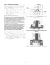
Figure 18. Parts provided for CT installation for one pole.
Figure 19. CT post mounted in the breaker back frame.
Figure 20. CT installation completed..
Wire
Fastener
1
2-13
Bolt
Top Copper
Bus
3
8-16
Bolts
Wire
Harness