


21
SECTION 7. EQUIPMENT
CONVERSION
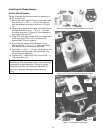
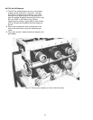
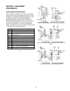
Installing Mounting Brackets
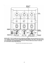
The equipment compartment contains the mating
portions of the fourth-wire disconnect and the neu-
tral sensor. The same disconnect assembly is used
for types AKD, AKD-5, and AKD-6 switchgear.
Mounting brackets for AKD, AKD-5, AKD-6, and
AKD-8 switchgear applications are included in the
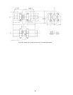
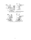
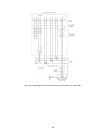
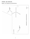
conversion kit. Figures 31, 32, 33, 34, and 35 are
mounting diagrams for the various applications.
Table 1 is a key to the numbers used in these figures
to indicate various hardware items.
Legend Description
225 Breaker portion of fourth-wire disconnect
226 Equipment portion of fourth-wire disconnect
229
Mounting bracket for AK-100 for AKD
compartments
230 10-32 x 1.375 inch mounting screw
231 Insulation
232 #10 lock washer
233 #10 flat washer
235
1
/8-20 flat washer
236
1
/8-20 lock washer
237
1
/4-20 nut
238
1
/4-20 x 1.25 inch mounting screw
239 Bracket
Table 1. Legend for number symbols appearing in Figures 31–
35.
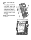
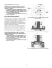
Figure 31. AK-50 & AKS-50 fourth-wire disconnect for AKD.
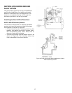
Figure 32. AK-75 & AK-100 fourth-wire disconnect for AKD-5 &
AKD-6.
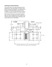
Figure 33. AK-100 fourth-wire disconnect for AKD.