


23
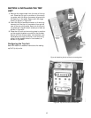
SECTION 8. TESTING AND TROUBLE-
SHOOTING
WARNING: Do not change taps on the current sen-
sors or adjust the trip unit settings while the
breaker is carrying current. Failure to adhere to
these instructions will void all warranties.
Testing
Before installing a converted breaker back into
service, perform the following steps:
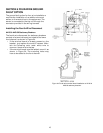
1. Verify that the trip unit is securely installed by
performing a continuity test on the CT wiring and
the trip unit.
a. Disconnect the black CT wires at each phase
sensor.
b. Check for continuity with a continuity tester or
VOM from the white lead of the phase A CT to
the white lead of the phase B CT.
c. Repeat this continuity test for the white leads
of the phase A and phase C CTs.
d. Measure the resistance across each phase
sensor and compare the values measured to
the values listed in Table 1.
e. Reconnect the black CT leads to all of the
phase sensors. Ensure that this is done before
continuing with performance testing of the
breaker.
CAUTION: In addition to the continuity test described
in Step 1 and before performance testing of the
converted breaker, each phase of the breaker
should be primary injected with a current level of
about 10%, but no more than 20%, of the CT rating.
During the application of test current, activate the
trip unit screen by depressing the battery button on
the trip unit face and check that the test current is
displayed on the screen for each phase tested. If the
trip unit fails to display the test current, stop the
test immediately and verify the installation of the
trip unit and wire harness before proceeding with
any additional testing.
WARNING: If the converted breaker is energized or
tested by primary injection with a sufficiently high
test current with a loose or open circuit between the
CTs and the trip unit, damage will occur to the trip
unit, wire harness, 36-pin trip unit connector, and
CTs. Failure to adhere to these instructions will void
all warranties.
2. Check the insulation on the primary circuit with a
1,000-volt Meggar.
3. Measure the resistance across the line and load
terminals for each phase using a micro-ohmme-
ter or millivolt tester. If the resistance differs
considerably from phase to phase, the electrical
connections may not be properly tightened or it
could also indicate improper contact wipe.
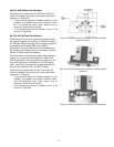
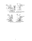
4. To verify that the breaker has been properly
retrofitted, perform a primary injection test on
each phase. This test will check the CTs, bus,
wiring harness, flux shifter, and trip unit as a
complete system.
a. A high-current, low-voltage power supply
should be connected across each line and load
terminal to simulate an overcurrent fault.
b. Set the long-time trip at 0.5 to minimize the
breaker stress.
c. When ground fault is installed, the test can be
performed by wiring two adjacent poles in
series or by using the GE Digital Test Kit, cat.
no. TVRMS2. This will prevent the breaker
from tripping because of an unbalanced cur-
rent flow.
CAUTION: Do not attempt to use GE Test Kit cat. no.
TVTS1 or TVRMS on this trip unit.
Trouble-Shooting
When malfunctioning is suspected, first examine the
breaker and its power system for abnormal condi-
tions such as the following:
• The breaker is not tripping in response to over-
current conditions or incipient ground faults.
• The breaker is remaining in a trip-free state
because of mechanical interference along its trip
shaft.
• The shunt trip (if present) is activating improp-
erly.
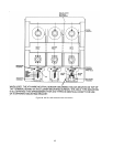
Nuisance Tripping on Ground Fault-Equipped
Breakers
When nuisance tripping occurs on breakers equipped
with ground fault trip, a probable cause is the
existence of a false ground signal. Each phase sensor
is connected to summing circuitry in the trip unit.
Under no-fault conditions on three-wire load circuits,
the currents add to zero and no ground signal is
developed. This current sum is zero only if all three
sensors have the same electrical characteristics. If
one sensor differs from the others (such as by a
different rating or wrong tap setting), the circuitry
can produce an output sufficient to trip the breaker.
Similarly, a discontinuity between any sensor and
the trip unit can cause a false trip signal.
The sensors and their connections should be closely
examined if nuisance tripping is encountered on any
breaker whose ProTrip trip unit has previously
demonstrated satisfactory performance. After dis-