


6
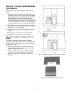
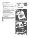
Installing the Flux Shifter Assembly
The installation procedure for the flux shifter
assembly, illustrated in Figure 3, varies depending
on the type of breaker and existing trip device. In
some cases, mounting holes must be added, termi-
nal blocks relocated, or breaker side rails removed.
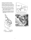
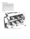
Breakers with EC or Power Sensor Trip Systems
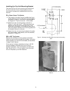
1. Drill the flux shifter mounting holes in the left
side of the breaker frame. The mounting hole
pattern is illustrated in Figure 4. A full-size tem-
plate is provided in the Appendix.
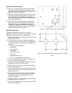
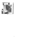
2. Mount the new flux shifter to the inside of the
side frame with the three screws, lock washers,
flat washers, and nuts supplied, as shown in
Figure 5. Insert the screws from the outside of
the side frame.
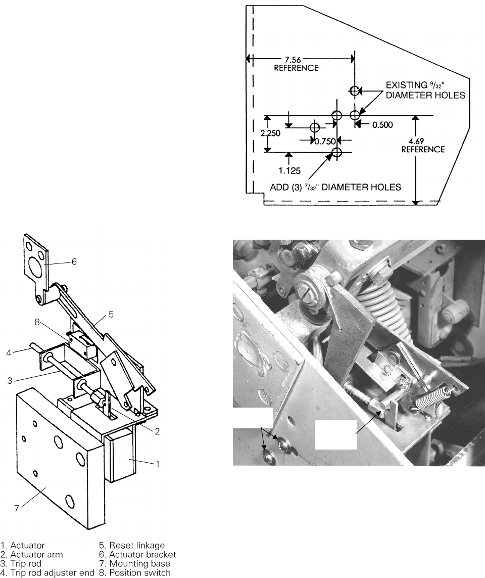
Figure 3. Flux shifter assembly.
Figure 4. Pattern for flux shifter mounting holes in the side frame.
Figure 5. Flux shifter assembly mounted to the side frame.
Flux Shifter
Assembly
Mounting
Screws