CHAPTER 3: INSTALLATION
EPM 6000 MULTI-FUNCTION POWER METERING SYSTEM – USER GUIDE 3–5
3.2 Electrical Installation
3.2.1 Installation Considerations
Installation of the EPM 6000 Power Metering System must be performed by only qualified
personnel who follow standard safety precautions during all procedures. Those personnel
should have appropriate training and experience with high voltage devices. Appropriate
safety gloves, safety glasses and protective clothing is recommended.
During normal operation of the EPM 6000, dangerous voltages flow through many parts of
the meter, including: Terminals and any connected CTs (current transformers) and PTs
(potential transformers), all input/output modules and their circuits. All primary and
secondary circuits can, at times, produce lethal voltages and currents. Avoid contact with
any current-carrying surfaces.
Do not use the meter or any I/O output device for primary protection or in an energy-
limiting capacity. The meter can only be used as secondary protection. Do not use the
meter for applications where failure of the meter may cause harm or death. Do not use the
meter for any application where there may be a risk of fire.
All meter terminals should be inaccessible after installation.
Do not apply more than the maximum voltage the meter or any attached device can
withstand. Refer to meter and/or device labels and to the Specifications for all devices
before applying voltages. Do not hi-pot/dielectric test any outputs, inputs or
communications terminals.
GE recommends the use of shorting blocks and fuses for voltage leads and power supply
to prevent hazardous voltage conditions or damage to CTs, if the meter needs to be
removed from service. CT grounding is optional.
If the equipment is used in a manner not specified by the manufacturer, the protection
provided by the equipment may be impaired.
Note
There is no required preventive maintenance or inspection necessary for safety. however,
any repair or maintenance should be performed by the factory.
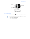
DISCONNECT DEVICE: The following part is considered the equipment disconnect
device.
A switch or circuit-breaker must be included in the end-use equipment or building
installation. The switch shall be in close proximity to the equipment and within easy
reach of the operator. The switch shall be marked as the disconnecting device for the
equipment.


