


5–16 EPM 6000 MULTI-FUNCTION POWER METERING SYSTEM – USER GUIDE
CHAPTER 5: COMMUNICATIONS
• Change to Modbus RTU Protocol (point 1): EPM 6000 meters are capable of switching
from the DNP Protocol to the Modbus RTU Protocol. This enables the user to update
the device profile of the meter. This does not change the protocol setting, as a reset
returns the meter back to DNP.
The Direct Operate - No Acknowledge (function 6) function will operate only with the
settings of Pulsed ON (Code = 1 of the Control Code field) once (Count = 01h) for ON
1 ms and OFF 0 ms.
5.4.4 32-Bit Binary Counter Without Flag (Object 20, Variation 4)
The counters support the Read function (function 1). A read request for Variation 0 will be
responded to with Variation 4.
Counters are used to communicate the hour readings measured by the EPM 6000 meter.
Refer to DNP Point Mapping on page 5–10 for details. These readings may be cleared by
using the Control Relay Output Block.
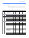
5.4.5 16-Bit Analog Input Without Flag (Object 30, Variation 5)
The analog inputs support the Read function (function 1). A read request for Variation 0 will
be responded to with Variation 5.
Refer to DNP Point Mapping on page 5–10 for details on the data measured by the analog
inputs.
• Health Check (point 0): The health check point indicates problems detected by the
EPM 6000. A value of zero (0000h) indicates the meter does not detect a problem; non-
zero values indicate a detected anomaly.
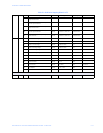
• Phase-to-Neutral Voltages (points 1 to 3): These points are formatted as two's
complement fractions. They represent a fraction of a 150 V secondary input. Inputs
greater than 150 V secondary will be pinned at 150 V secondary.
• Phase-to-Phase Voltages (points 4 to 6): These points are formatted as two's
complement fractions. They represent a fraction of a 300 V secondary input. Inputs
greater than 300 V secondary will be pinned at 300 V secondary.
• Phase Currents (points 7 to 9): These points are formatted as two's complement
fractions. They represent a fraction of a 10 A secondary input. Inputs greater than
10 A secondary will be pinned at 10 A secondary.
• Total Real and Reactive Power (points 10 and 11): These points are formatted as two's
complement fractions. They represent a fraction of 4500 W secondary in normal
operation or 3000 W secondary in open delta operation. Inputs above/below ±4500 or
±3000 W secondary will be pinned at ±4500 or ±3000 W secondary, respectively.
• Total Apparent Power (point 12): This point is formatted as a two's complement
fraction. It represents a fraction of 4500 W secondary in normal operation or 3000 W
secondary in open delta operation. Inputs above/below ±4500 or ±3000 W secondary
will be pinned at ±4500 or ±3000 W secondary, respectively.
• Power Factor (point 13): This point is formatted as a two's complement integer. It
represents power factors from –1.000 (0FC18h) to +1.000 (003E8h). When in open
delta operation, the total power factor (point 13) is always zero.