


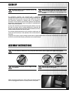
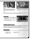


Step 3
If the table needs adjustment loosen both lock levers
and readjust the table position until the square is flat
against the table and the sanding drum. To allow
for more or less rear tilt adjust the table stop rod as
needed.
Step 4
Make sure the pointer reads 0°. If the pointer needs
to be adjusted loosen the screw and adjust to the
correct position.
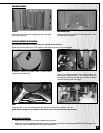
Step 5
Once the table has been adjusted and locked in place at 90° adjust the 90° table stop rod to butt against the under-
side of the table allowing you to return to 90° repeatedly without further adjustments.
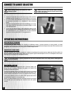
SETUP FOR BEVEL SANDING
1. Make sure the correct oblong opening table insert is in
place. See the accompanying SELECTION GUIDE
(page 10) to select the correct TABLE INSERT for the
spindle being used.
2. Loosen both locking levers and tilt the table until the
pointer is at the desired angle.
3. Hold the table in place and tighten both locking levers.
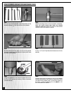
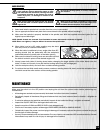
CHANGING SANDING SLEEVES
Make sure that the switch is in “OFF” position and that the power cord is unplugged.
Note: Installing or changing sanding sleeves is best performed with the spindle removed from the machine.
Refer to page 8 - “Installing the sanding sleeves” for step by step instructions.
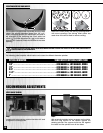
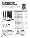
REPLACEMENT SANDING SLEEVES
Replacement sleeves can be purchased in varying grits (depending on availability) from any local tool or abrasives
dealer in the following sizes:
• 1/4" DIAMETER X 6 " LONG • 1-1/2" DIAMETER X 5 1/2 " LONG
• 1/2" DIAMETER X 6 " LONG • 2” DIAMETER X 5.5” LONG
• 5/8" DIAMETER X 6 " LONG
11
90° TABLE
STOP ROD