


English
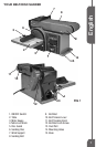
Belt/Disc Sander
Operator’s Manual GBDS450
WARNING: The belt tension lever is
spring loaded. Be careful when pushing the
tension lever back into place to avoid personal
injury.
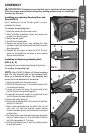
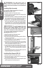
Installing Table Assembly
To Install the Table Assembly for Use with
Sanding Disc (FIG 7,8, 9)
1.Unplugthesanderfromthepowersource.
2.Insertthepositionpinontablesupportintotheupperhole
onthemachine.SeeFIG7.
3.Inserttablelockknob(1)throughaatwasherandthe
tablesupportslotandintothethreadedholeofbaseas
shownonFIG7.Turnandtightenthetablelockknob.
4.Loosenthethreehexheadnutsatbottomoftablesupport
(FIG9)andadjusttabletomakesurethetableedgeis
nomorethan1/16"(1-2mm)fromthesandingsurface.
Tightenthethreehexheadnuts.Re-tightenthelockknob.
WARNING:To avoid trapping the work
piece or your finger between the table and
sanding disc, the table edge must be no more
than 1/16" (1-2mm) from the sanding surface.
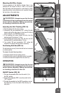
To Install the Table Assembly for Use with
Sanding Belt (FIG 9, 10, 11)
1.Unplugthesanderfromthepowersource.
2.Removetheworksupportifitison.
3.Placethebeltbedintheverticalsandingposition.Referto
"PositioningtheBeltBed".
4.Insertthepositionpinontablesupportintotheposition
holeonthebeltbedasshownonFIG10.
5.Inserttablelockknobthroughaatwasherandthetable
supportslotandintothethreadedholeasshownonFIG
10.Turnandtightenthetablelockknob(1).
6.Loosenthethreehexheadnutsatbottomoftablesupport
andadjusttabletomakesurethetableedgeisnomore
than1/16"(1-2mm)fromthesandingsurface.Re-tighten
thelockknob.
7.Adjusttheprotectionplate(2)underthetabletocoverthe
exposedsandingbeltforextraprotection.
Installing Work Support (FIG 12)
1.Unplugthesanderfromthepowersource.
2.Placetheworksupport(1)overtheholeinthesideofthe
toolhousingasshowninFIG12.
3.Usingawrenchprovided,fastentheworksupportinplace
withthewasherandhexheadscrew(2).
FIG 8
FIG 9
FIG 10
1
FIG 7
1
FIG 11
2