


9
English
ASSEMBLY
WARNING: Always be sure that the tool is switched off and unplugged
from the power source before adjusting, adding accessories, or checking a
function on the tool
.
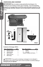
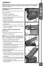
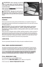
Installing or replacing Sanding Disc and
Guard (FIG 3)
One6"sandingdisc(3)andthediscguard(1)arepre-
installedatthefactory.
To replace the sanding disc
1.Unplugthesanderfromthepowersource.
2. Using a Phillips screwdriver, loosen and remove two
screws(2)onthediscguard.
3.Removethediscguard.
4.Peelofftheoldsandingdisc.
5. Remove thebacking from a new sanding disc. Align
perimeterofdiscwithsandingplateandrmlypressthe
discintoposition.
6.Reinstallthediscguard asshownonFIG3.Thedisc
guardcanbeadjustedupanddowntocoversanding
discformoreprotection.
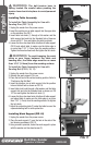
Installing or Replacing Sanding Belt
(FIG 4, 5, 6)
Asandingbeltispre-installedandalignedatthefactory.
To replace the sanding belt
NOTE:Use 4"x36" (100mm x 914mm) sanding
belt. On the smooth side of the sanding belt,
there is a directional arrow. The sanding belt
must run in the direction of the arrow.
1.Unplugthesanderfromthepowersource.
2.PulltheBeltTensionLever(1)atdirectionshownonFIG
4toreleasebelttension.
3.Loosenandremovethescrew(3)oneachsideofbelt
bed(8).Removetheupperbeltguard(5).
4.Loosenandremovetwoscrews(4)oneachsideofbelt
bed(8).Removethelowerbeltguard(7).
5.Removetherubberbump(6).
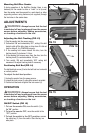
6.Removetheoldsandingbelt(10)fromdriver(9)andidler
rollers(10).SeeFIG6.
7.Placeanewsandingbeltoverthedriverroller(9)and
idler roller (10) with the direction arrows running
counter-clockwise.Besurethesandingbeltiscentered
onbothrollers.
8.Putrubberbump,lowerbeltguardandupperbeltguard
backon.Tightenscrews(3,4)onbothsidesofthebelt
bed(8)tokeepguards(5,7)inplace.
9.Pushthebelttensionlever(1)backintolockingposition
toapplybelttension.
FIG 3
1
2
3
FIG 4
1
2
FIG 5
3
4
8
5
7
6
FIG 6
9
10
11