


Copyright Gianni Industries, Inc. All Rights Reserved.
P-MU-DG600 Ver. B Publish:2004.08.27 Page: 3/ 6
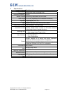
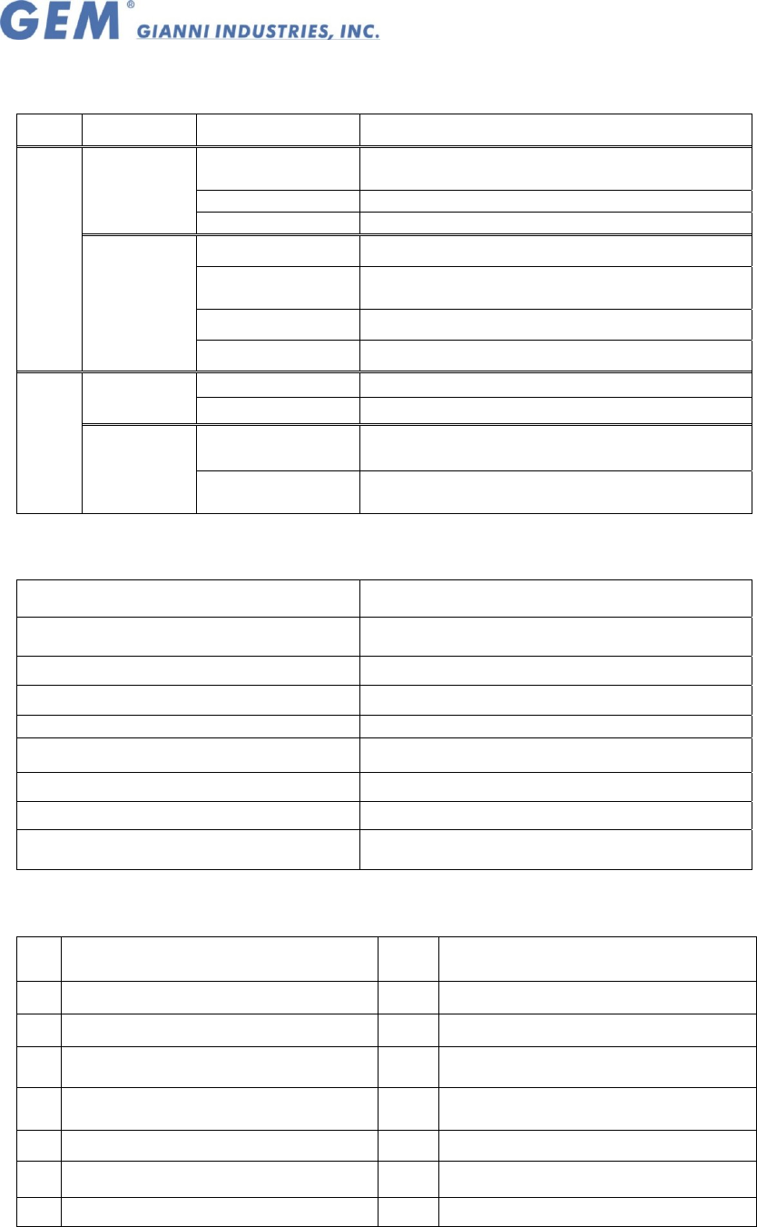
III. The indicator signal chart:
Sound and LED indicator:
Mode Signal Condition
Yellow LED
(Flashing slowly)
Power on, Stand-by
Green LED Valid entry, lock relay active
User Signals
Red LED Warning, Invalid Card or code, Tamper
Yellow LED Programming mode entered
Yellow LED
(Flashing)
Card has been read, awaiting input of PIN
codes
Green LED Slot Position ready to store card
LED
signal
Programming
Signals
Red LED Memory slot already has a card registered
1 Beep
Card presented、Any key pressed
User Signals
4 Beeps
Invalid card 、 Data computing error
1 Beep
The input data is correct 、 Enters or Exit
Programming mode
Sound
signal
Programming
Signals
4 Beeps
Input mistake, or other operation mistakes,
duplicate card
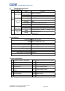
Default Settings:
Access Mode Read Card only (00)
Format
All bits(44-bit or 26~37-bit)
Card register None
Master Codes 12345 (5 digits)
(All) Alarm function Defeat able (00)
Relocking timer 5 seconds
Pressed key delay time (Time Out) 5 seconds
Waiting input PIN codes time 5 seconds
Setting mode delay time 25 seconds
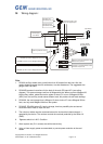
Terminal connections:
CN1 Contacts on block for the system CN2 Contacts on block for auxiliary reader
12 + 8.5 ~ 16 Vdc 12 + 8.5 ~ 16 Vdc
V
GND 、 Power ground
V
GND 、 Power ground
D Electrified lock D1
DATA1 Wiegand Data 1
C
Electrified lock, Alarm Common
(COM)
D0 DATA0 Wiegand Data 0
A Alarm Common LED LED contact
E Door reed switch BEEP Beeper contact
B Request-to-exit