


Copyright Gianni Industries, Inc. All Rights Reserved.
P-MU-DG600 Ver. B Publish:2004.08.27 Page: 4/ 6
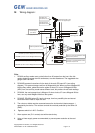
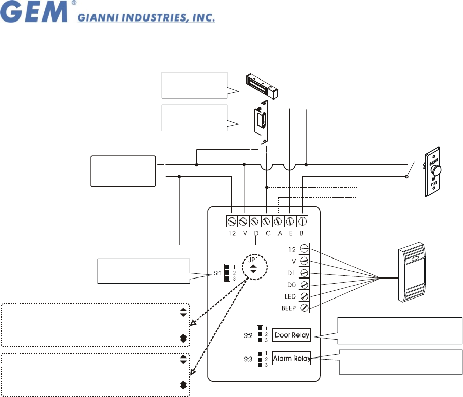
IV. Wiring diagram:
Fail-Safe Lock
St 2 connect to 1-2
Contact door switch or the
electric lock signal output
Push Button
External relay start
the warning system
Auxiliary Reader
(Wiegand Format)
Connect to 1-2;C and D contact is N.C.
Connect to 2-3; for N.O.
Connect to 1-2;C and A contact is N.C.
Connect to 2-3; for N.O.
Fail-Secure Lock
St 2 connect to 2-3
*Linear supply recommended
Power supply
(10~15Vdc)
Insert 2-3 position to reset
DG-600E Jp1 leads to Wiegand 44 bits format
DG-600H Jp1 leads to all Wiegand format
DG-600E Jp1 short-circuit to Wiegand 26 bits format
DG-600H Jp1 short-circuit to Wiegand 26 bits format
Note:
1. DG-600 auxiliary reader must not be further than 20 meters from the host. Also this
reader should be nearer than 30 centimeters, to avoid disturbance. The suggested wire
gauge is #22~26 AWG.
2. DG-600E important instructions: At the back of the main PC board JP1 (see wiring
diagram). The system storage card form is Wiegand 44 bits. When you have Wiegand 26
bits auxiliary reader, please do use the solder to short JP1 to turn to Wiegand 26 bits
(HEX) form, the auxiliary reader stores different card, this produce invalid card readings
3. DG-600H, the card storage form is Wiegand. If short-circuits JP1 turns Wiegand 26 bits
form, can only read Wiegand 26 bits to the system.
4. DG-600E, DG-600H when JP1 has the change, there’s a possibility the card stored
would be invalid. Reset to input the card.
5. The varistor or diode must be connected across the lock terminal (electromagnet...)
operated by the device. The vartistor controls the overload produced by the strike coil
(EMP).
6. Egresses switch is in N.O. Condition.
7. Alarm system use (C.A. contact) start with external relay.
8. Using a Linear supply power recommended, to prevent power reduction at the card
reader.