


9
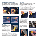
Attaching the laser light assembly
Take the laser light arm (19) and position it on the left
hand side of the saw. Fit the laser light arm locking knob
(20) through the arm and into the saw. Tighten the
knob to securely fasten the arm onto the saw.
Fit the laser light assembly (21) onto the end of the arm.
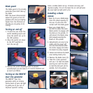
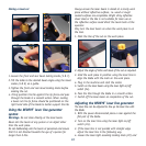
Rip fence
Fit the rip fence (15) onto
the table (11) on the left
hand side of the blade.
The rip fence locking lever
will need to be loosened in
order to fit the fence onto
the table. Once the fence is
positioned on top of the table
push down on the rip fence locking lever (16) to secure
the fence in position. If the rip fence is not secured
to the table lift up the locking lever and turn it in a
clockwise direction to give it a tighter grip. Push down
on the locking lever to secure the fence in position.
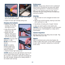
Mitre gauge
The mitre gauge (17) fits over the top of the rip fence
and is used to cut tiles at a particular angle. The
mitre gauge can be adjusted from 0° to 45° and in
conjunction with the fence is used to guide the work
piece through the blade.
To adjust the angle of the mitre gauge loosen the mitre
gauge locking knob (18) at the top of the unit and
position the mitre gauge at the desired angle.
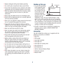
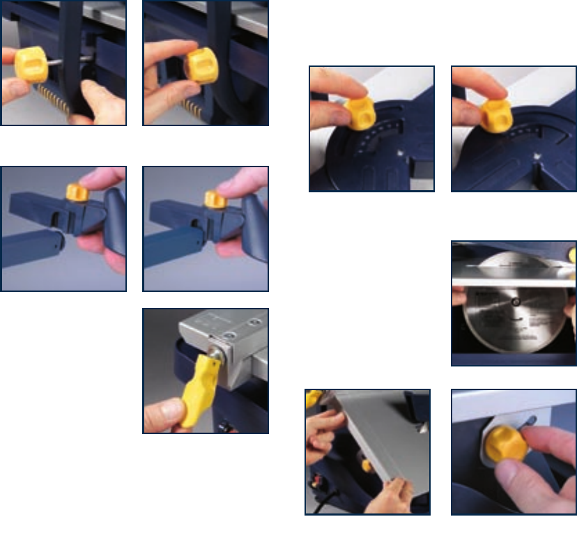
Bevel lock
The bevel lock is designed to
set the table at the desired
bevel angle. The tile cutting
saw bevel cuts from 0° to
45°. To adjust the bevel angle
loosen the front and rear
bevel locking knobs (5 & 7).
Tilt the table to the desired
angle and tighten the bevel
locking knobs to secure the
table in position.