


9
Note.
It may be necessary to rotate the handle
anticlockwise to be able to slide the rip fence over the table
and then clockwise before locking the handle in position.
5. Attach the mitre gauge (30) onto the table by sliding it into
the mitre gauge slot.
6. Screw the push stick screw and nut into the hole at the
rear of the saw (next to the push stick storage area).
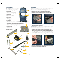
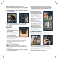
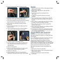
Mounting to a
workbench
1. The band saw features four
holes in the base for mounting
to a workbench.
2. It is best to attach the band
saw to a firm, stable surface
at a convenient working
height. A workbench is ideal.
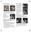
3. Drill four holes in the workbench to match the four holes
in the base of the saw.
4. Attach the band saw to the work bench using bolts
(inserted from the top), lock washers and nuts
(not supplied).
Upper blade guide adjustment
WARNING. Always ensure that the saw is switched
off and unplugged from the power supply before making
any adjustments.
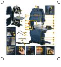
1. The upper blade guide (20) protects against unintentional
contact with the saw blade.
2. In order for the upper blade guide to provide adequate
protection against contact with the band saw blade (25),
it must always be set as close as possible against the
workpiece (maximum distance 3mm).
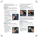
3. To adjust the height of the
upper blade guide rotate the
blade guide knob (21). Rotate
in a clockwise direction to
move the blade guide up,
rotate in an anti-clockwise
direction to move the blade
guide down.
4. The upper blade guide
consists of a thrust bearing
that supports the band saw
blade from the rear and two
guide pins that provide
lateral support, these need
to be readjusted after every
band saw blade change or
tracking adjustment.
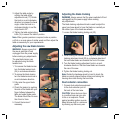
Thrust bearing adjustment
1. To adjust the thrust bearing loosen the thrust bearing
locking screw using the 3mm hex key (36) supplied.
2. Adjust the thrust bearing position until it is 0.5mm
away from the band saw blade. When the band saw
blade is turned by hand it should not make contact with
the thrust bearing.
3. Tighten the thrust bearing locking screw.