


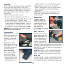
11
the bevel lock and pull out
the 0° bevel adjuster (18).
Adjust the saw arm to the
desired bevel angle.
WARNING. Be sure to tighten
the bevel lock before making
a cut. Failure to do so could
result in the saw arm moving
during the cut and cause
serious personal injury.0°
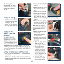
Bevel adjuster
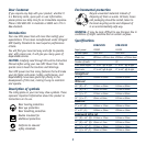
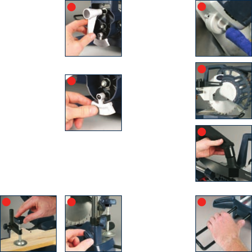
The bevel adjuster (18) needs
to be pulled out before the
bevel angle can be adjusted
(fig. F).
To return the saw arm to the
vertical (0° bevel) position
move the saw arm to the
left and push in the 0°
bevel adjuster.
Return the saw blade to the vertical position, it will
automatically stop at the 0° bevel position. Tighten the
bevel lock.
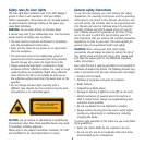
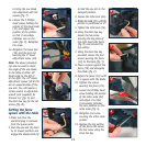
Clamp assembly
The clamp assembly (10) can be mounted to the fence, either
side of the saw blade, to suit the task at hand (fig. G).
Use the clamp assembly lock (11) at the back of the fence
to secure the clamp assembly in position (fig. H).
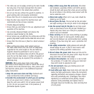
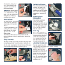
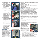
Spindle lock button
The spindle lock button (26)
prevents the blade in the
saw from rotating (fig. I).
Depress and hold the spindle
lock button while installing,
changing, or removing the
blade.
Rotating lower
blade guard
The rotating lower blade
guard (12) provides
protection from both sides of
the blade (fig. J). It retracts
over the upper blade guard
(9) as the saw is lowered
into the workpiece.
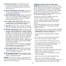
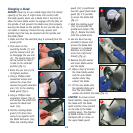
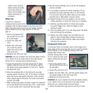
Dust bag
The dust bag (15) fits over
the dust extraction port (27).
For more efficient operation,
empty the dust bag when
it is no more than half full.
This allows better air flow
through the bag (fig. K).
Attaching the side bars
The side support bars (37)
help to support the material when working with long
workpieces. There are two
location holes (33) for a
support bar on either side of
the table. Loosen the lock
screws (34) with the 6mm
hex key. Ensure the side
bars are fully inserted before
using them to support the
workpiece (fig. L).
G H
E
F
I
J
K
L