


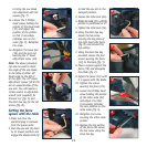


13
to bring the saw blade
into alignment with the
square (fig. T).
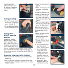
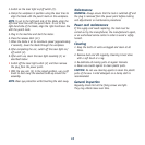
13. Loosen the 2 Phillips
head screws holding the
pointer of the bevel scale
(17) and adjust the
position of the pointer
so that it accurately
indicates zero on the
scale (fig. U). Retighten
the screw.
14. Retighten the bevel lock
(16) and the lock nut
securing the 0° bevel
adjustment screw (30).
Note. The above procedure
can also be used to check
the angle of the saw blade
to the table at either 45º
bevel angle to the left or
to the right. The 45° bevel
adjustment screws (28 & 29)
are on opposite sides of the
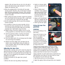
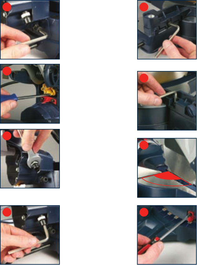
saw arm. You will require a
13mm wrench or adjustable
wrench (not supplied) for
the lock nut (fig. V) and
the 6mm hex key for the set
screws (fig. W).
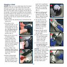
Setting the fence
square with the table
1. Make sure that the
electrical plug is removed
from the power point.
2. Push the saw arm (5) down
to its lowest position and
engage the release knob (6)
to hold the saw arm in the
transport position.
3. Loosen the mitre lock (25).
4. Rotate the table (21) until the
pointer is positioned at 0º.
5. Tighten the mitre lock (25).
6. Using the 6mm hex key
loosen the hex screw
securing the top piece of
the right hand side fence
(fig. X) and remove this
top section.
7. Using the 6mm hex key
provided, loosen the four
screws securing the fence
(19) to the base (fig. Y).
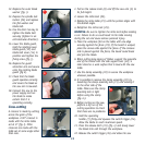
8. Place a square against the
fence (19) and alongside
the blade (fig. Z).
9. Adjust the fence (19) until
it is square with the blade.
10. Tighten the screws
securing the fence (19).
11. Loosen the Phillips head
screw holding the pointer
of the mitre scale (22)
and adjust it so that
it accurately indicates
the zero position on the
mitre scale (fig. a).
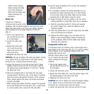
12. Retighten the screw
securing the mitre scale
pointer.
13. Replace the top section
of the fence and secure
the hex screw using the
6mm hex key.
T
U
V
W
X
Y
Z
90°
a