


12
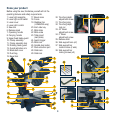
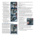
Attaching the side bars
The side support bars (36) help
to support the material when
working with long workpieces.
There are two location holes
(37) for a support bar on either
side of the table. Ensure the
side bars are fully inserted
before using them to support the
workpiece (Fig. L).
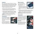
The side support bar locking
screws (38) must be tightened
to secure the support bars in
position (Fig. M).
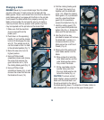
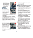
Trench depth adjustment
In its normal position, the trenching stop (31) permits the
saw blade to cut right through a workpiece. When the saw
arm is lifted, the trenching stop can be moved to the left so
that the trenching depth adjustment screw (30) contacts the
stop as the saw arm is lowered. (Fig. N). This restricts the
cut to a “trench” in the workpiece. The depth of the trench
can be adjusted with the trenching depth adjustment screw
(30) (Fig. O) and locked in position with the trenching depth
lock nut (32).
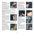
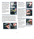
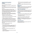
Turning on and off
1. To turn the saw on depress
and hold the on/off trigger
switch (24) (Fig. P).
2. To turn the saw off release the
on/off trigger switch (24).
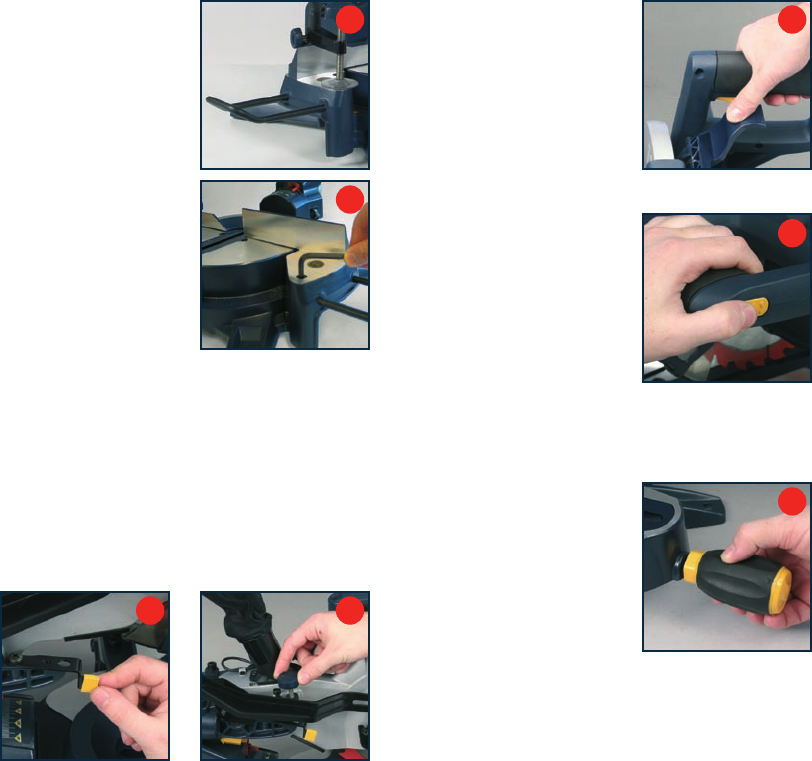
Turning on the REDEYE
®
laser line generator
The REDEYE
®
laser line
generator emits 2 intense narrow
beams of pure red light to guide
you as you cut. It improves
operator cutting vision, enables
faster set-up, increases accuracy
and improves safety. To turn on
the laser lines press the laser
light on/off switch (2) (Fig. Q).
To turn off the laser press the laser light on/off switch
(2) one more time.
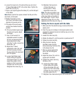
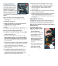
Setting the table square with the blade
1. Make sure that the electrical
plug is removed from the
power point.
2. Push the saw arm (5) down
to its lowest position and
engage the release knob (6)
to hold the saw arm in the
transport position.
3. Loosen the mitre lock (25) (Fig. R).
4.
Rotate the table (21) until the pointer is positioned at 0º.
5.
Tighten the mitre lock (25).
L
M
O
N
P
Q
R