


9
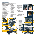
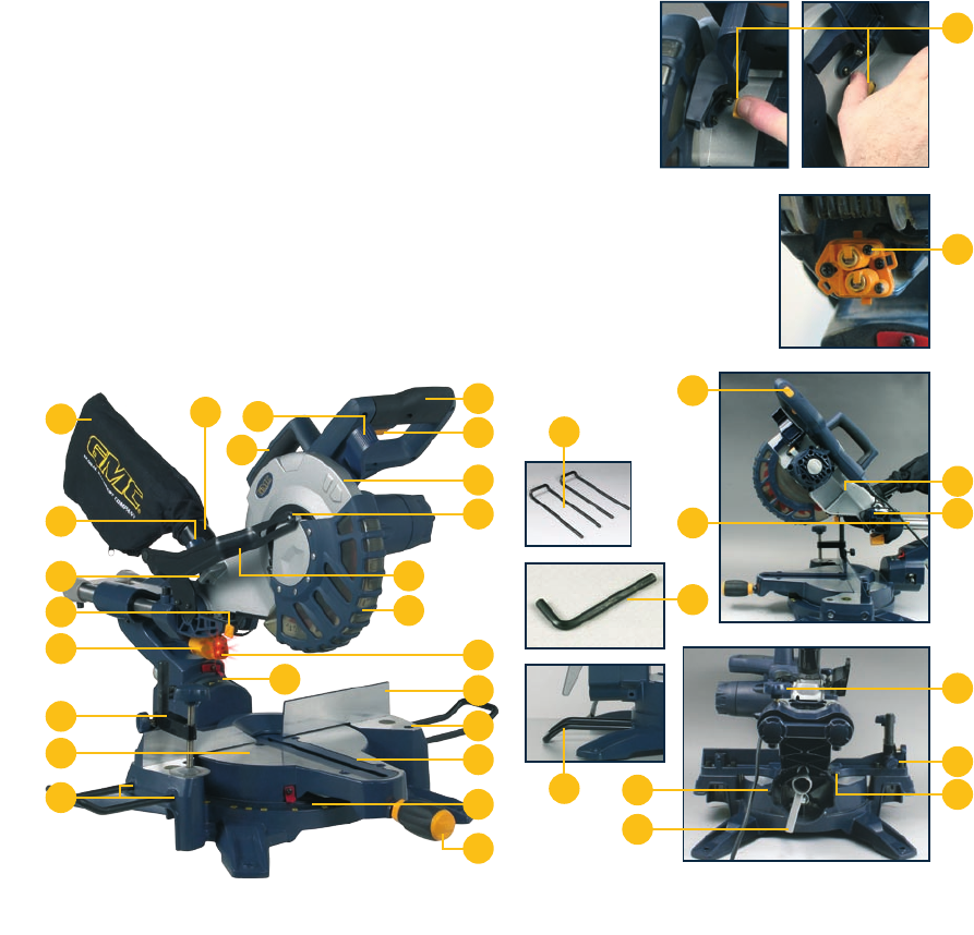
Know your product
Before using the saw, familiarise yourself with all the
operating features and safety requirements.
1. Laser light assembly
2. Laser light on/off switch
3. Laser cover
4. Laser pitch control
5. Saw arm
6. Release knob
7. Operating handle
8. Carrying handle
9. Upper fixed blade guard
10. Clamp assembly
11. Clamp assembly lock
12. Rotating blade guard
13. Guard retraction arm
14. Blade bolt cover
15. Dust bag
16. Bevel lock
17. Bevel scale
18. Fence
19. Stabiliser bar
(LSMS250A only)
20. 6mm Hex key
21. Mitre table
22. Mitre scale
23. Table insert
(kerf plate)
24. Switch trigger
25. Mitre lock
26. Spindle lock button
27. Dust extraction port
28. Slide bars
29. Slide lock
30. Trenching depth
adjustment screw
31. Trenching stop
32. Trenching depth
lock nut
33. 45° Bevel
adjustment screw
34. 0° Bevel
adjustment screw
35. Release latch
36. Side support bars (x2)
37. Side support bar
location holes (2 sets)
38. Side support bar
locking screws (x2)
33
11
16
34
29
17
28
6
5
2
20
36
4
30
32
15
31
13
27
8
3
10
21
37
24
7
35
14
9
1
12
25
18
22
23
19
LSMS210A
LSMS250A
26
38