


10
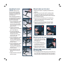
Assembling the stand
CAUTION. Always pull out
the mains power plug before
carrying out any maintenance,
conversion or assembly work
on the table saw.
When assembling the stand it is
recommended that the screws are
only lightly tightened until the
stand is fully assembled.
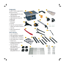
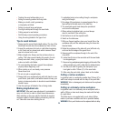
1. Use four carriage bolts, spring
washers, flat washers and
nuts (s) to fit a short middle
brace (q) between two stand
legs (m) (Fig. A).
2. Connect a second short
middle brace (q) to the second
pair of stand legs (m).
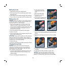
3. Use eight carriage bolts,
spring washers, flat washers
and nuts (s) to fit the
remaining two long middle
braces (p) (Fig. B).
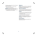
4. Use four carriage bolts, spring
washers, flat washers and
nuts (s) to attach each short
upper brace (n) to the top of
the stand (Fig. C).
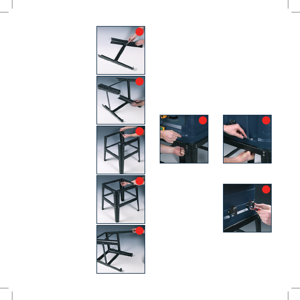
5. Use four carriage bolts, spring
washers, flat washers and
nuts (s) to attach each long
upper brace (o) to the top of
the stand (Fig. D).
6. Add a rubber foot (r) to the
base of each stand leg (m)
(Fig. E).
7. Tighten all bolts and place the
stand on its feet.
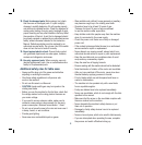
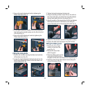
Fitting the table saw to the stand
1. Make sure the blade is completely retracted into the
table top.
2. Align the holes on the stand with the matching holes
in the base of the table saw, the holes at the front of
the table top are further apart than the holes at the back
of the table saw housing.
3. Secure the front of the table saw to the stand using
2 65mm hex head bolts with 2 flat washers, spring
washer and nut (t) (Fig. F).
4. Secure the rear of the table saw to the stand using
2 50mm hex head bolts with 2 flat washers, spring
washer and nut (u) (Fig. G).
F
G
5. Fully tighten all screws and nuts.
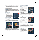
Fitting the push stick mounting brackets
1. Fit the 2 push stick mounting
brackets to the right hand side
of the table saw.
2. Use 2 Phillips head screws
and washers (i) to attach each
mounting bracket (Fig. H).
3. Slide the push stick into the
brackets to hold it in position.
Fitting the height adjustment handle
and locking knob
1. Fit the height adjustment locking knob onto the shaft at the
front of the table saw ensuring that the flat on the inside of
the knob locates on the flat at the rear of the shaft (Fig. I).
A
B
H
C
E
D