


28
307–758
CIRCUIT
BOARD
REPLACEMENT
WARNING
To
reduce the risk of serious injury
, follow the illus
-
trated Pressure Relief Procedure warning on
page 24 whenever you are instructed to relieve
pressure.
NOTE: Read the GENERAL REPAIR INFORMATION
on
page 24 before doing this procedure.
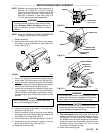
NOTE:
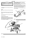
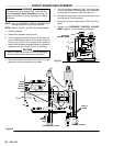
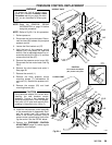
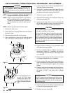
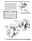
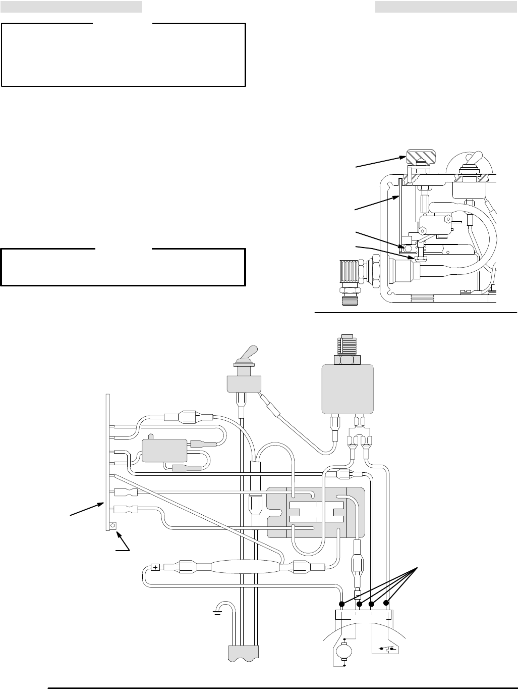
Refer to Fig 28–1 and 28–2 for this procedure.
1.
Relieve pressure.
2.
Remove the pressure control cover
.
3. Turn the pressure control knob to the minimum set-
ting
to release spring tension on the board. Check to
be sure only three or four threads of the pressure
control knob shaft are exposed below the pressure
adjustment
nut (S). Loosen the nut, if necessary
.
CAUTION
Step 2 is essential to reduce the risk of damaging
the
circuit board while removing or installing it.
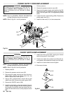
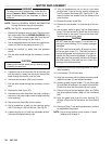
4. Disconnect
all seven wires from the board. Pay close
attention
to where connections are made.
5.
Pull
out the plastic-tipped pin (330). Push the bottom
of the circuit board (72) toward the wall of the pres-
sure
control and carefully slide the board out.
6. Reinstall
the new board in the pressure control at the
same
angle as it was removed.
7. Reconnect all wires. Ease the pin (330) into the re-
tainer.
8. Perform the PRESSURE CONTROL ADJUST-
MENT,
page 30, if you installed a new board.
PRESSURE
CONTROL KNOB
330
S
Fig
28–1
01230
72
Fig 28–2
330
72
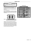
AC1
AC2
G1
G2
_
+
WHITE
BLUE
YELLOW
RED
GREEN
BLACK
WHITE
GROUND
WIRE
BLACK
POWER
SUPPL
Y CORD
THERMAL SWITCH
MOTOR
MOTOR
LEADS