


34
307–758
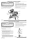
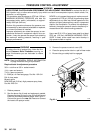
MOTOR REPLACEMENT
WARNING
To
reduce the risk of serious injury
, follow the illus
-
trated Pressure Relief Procedure warning on
page 24 whenever you are instructed to relieve
pressure.
NOTE: Read the GENERAL REPAIR INFORMATION
on
page 24 before doing this procedure.
NOTE:
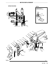
See Fig 35–1 except where noted.
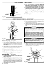
1.
Remove the pressure control cover
. Disconnect the
four
motor leads. See the
WIRING DIAGRAM
in Fig
35–1. Remove the conduit seal (26) from the con-
duit
elbow (345) coming into the control.
2. Use
an adjustable wrench to loosen the conduit con
-
nector
nut (345) at the pressure control (77).
3. Swing the conduit (1) away from the pressure
control.
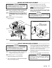
4. Pull
the motor leads through
the connector
, one at a
time.
CAUTION
Always pull the motor leads one at a time to avoid
loosening
the terminals.
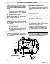
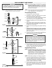
5. Loosen
the nut of the connector (29) at the motor and
pull
the conduit (1) away from the motor
, then pull the
leads
through the conduit, one at a time.
6.
Unscrew the connector (29) from the motor
.
7. Pull
the motor leads through
the connector
, one at a
time.
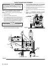
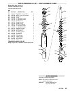
8. Remove
the front cover (57).
9.
Unscrew the suction tube from the pump, holding a
wrench on the pump intake valve to keep the pump
from
loosening.
10.
Disconnect the hose (68) from the pump.
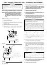
1
1.
Use a screwdriver to push up the retaining spring
(42).
Push the pin (43) out the rear
.
See Fig 25.
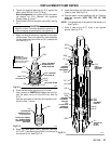
12.
Loosen the jam nut (41) with an adjustable wrench.
Unscrew
the displacement pump.
13. Turn the displacement rod so the pin hole faces
straight back. Insert a hex key wrench through the
hole to unscrew the screw (25). See Fig 32–1.
Re-
move the other two screws from the recess of the
drive
housing.
14.
Remove the motor shield (58).
15. Remove
the two screws (14) from the top of the mo
-
tor.
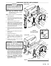
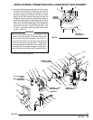
16. Use a plastic mallet to gently tap the displacement
pump
(74) from the rear to loosen
the drive housing
from
the front of the motor
. Then pull the drive hous
-
ing
away from the of the motor
.
DO
NOT allow the gear cluster (71) to fall when re
-
moving
the drive housing (73). It is easily damaged
if
dropped.
DO NOT lose the thrust balls (8) located at each
end of the gear cluster (71). The balls are heavily
covered
with grease
and usually stay in the gear re
-
cesses, but they could be dislodged. If caught be-
tween
gears and not removed, the balls will damage
the drive housing. If the balls are not in place, the
bearings
will wear prematurely
.
CAUTION
17. Remove
the four motor mounting screws (7) and
re
-
lated
hardware.
18.
Lift the motor (75) of
f the frame.
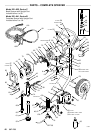
19. Align
the new motor with the frame mounting holes.
Install the screws (7) and related hardware.
20. Liberally
grease the gear cluster (71) and pinion
gear
(A)
and pack all bearings in the motor front end bell.
Check
to be sure the thrust balls (8) are in place.
21. Place the bronze-colored washer (69a) and THEN
the silver-colored washer (69b) on the crankshaft
(69).
22. Align the gears and push the drive housing (73)
straight onto the front of the motor and the locating
pins.
23. Starting
at Step
17 and working backwards, continue
to
reassemble the sprayer
.
NOTE:
Use a turning motion on the conduit (1) when
feeding wires through it.