


36
307–758
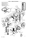
DISPLACEMENT PUMP REPAIR
WARNING
To
reduce the risk of
serious injury
, follow the
Pres-
sure
Relief Procedure
warning on page 24 when
-
ever
you are instructed to relieve pressure.
NOTE: Read the GENERAL REPAIR INFORMATION
on
page 24 before doing this procedure.
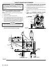
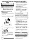
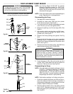
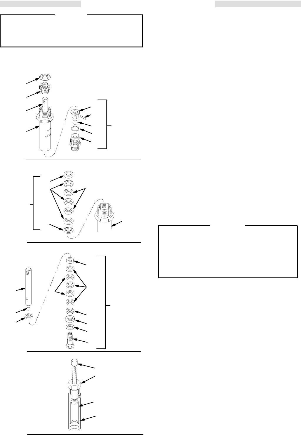
Fig 36–1
204*
221*
220
219
202*
223
205
216
224
INTAKE
VALVE
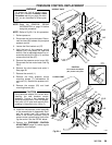
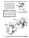
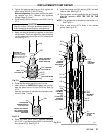
Fig 36–2
*209
*213
207*
*208
219
THROAT
PACKINGS
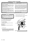
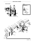
Fig 36–3
210*
212*
215*
203*
214*
222
224
*225
211
*206
PISTON
ASSEMBLY
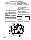
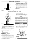
Fig 36–4
219
B
A
0028
218
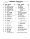
NOTE:Use Packing Repair Kit 222–587. An asterisk
following a reference number, i.e., (210*), indi-
cate
that the part included in the kit. For the best
results,
use all the new parts in the kit even if the
old
ones still look good.
NOTE: Clean
and inspect parts after disassembling
the
pump.
Replace worn or damaged parts.
Disassembling the Pump
1. See
page 38 to remove the pump.
2. Unscrew the intake valve (223) from the cylinder
(219).
Remove all parts. See Fig 36–1.
3. If
no further service is needed,
reassemble the intake
valve.
Be sure you use a new gasket (202*).
4. Remove the packing nut (216) and plug (205). See
Fig
36–1.
5. Use
a plastic mallet to tap the piston rod (224) down,
then pull the rod out through the bottom of the
cylinder
(219). See Fig 36–1.
6. Remove the throat packings and glands.
See Fig
36–2.
7. Clamp
the flats of the piston rod in a vise. Loosen
the
retaining nut (211). Unscrew the piston valve (222)
from
the rod. Remove all
parts from the piston valve
(222).
See Fig 36–3.
8.
Remove and
clean the sleeve (218). Use ONL
Y the
special sleeve removal tool, P/N 222–586.
Always use the special sleeve removal tool to re-
move the sleeve. Other removal methods could
cause the pump to rupture, resulting in serious
bodily
injury
.
If the sleeve cannot be removed easily
using the tool,
return the sleeve and cylinder to your
Graco
distributor for removal.
WARNING
9. Screw
the large nut (B) of the tool into the
top of the
cylinder (219). Screw down the rod (A) to push the
sleeve
out. Remove the tool. See Fig 36–4
.
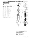
Reassembling the Pump
NOTE: Alternate
leather and plastic packings as shown
in Fig 37–1. The lips of the throat “V” packings
must
face down. The lips of the piston “V” pack
-
ings must face up. The lips of the U–cup seal
(203*)
face down. Incorrect installation damages
the
packings and results in pump leaking.
NOTE:
Soak leather packings in oil before using them.
1. Check
the outside of the piston rod (224) and the in
-
side of the sleeve (218) for scoring or scratches. If
these
parts are damaged, new packings will not seal
properly.
Replace these parts if needed.
2. Stack
the backup washer (214), seal (203*),
female
gland (215*), alternate packings (212*,206*), and
then male gland (210*) onto the piston valve (222).
See
Fig 36–3.