


Maintenance
332198C 11
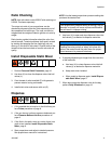
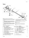
Install Restrictors or Plugs
Two 0.024 in. restrictors are installed with the gun. An
extra 0.032 in. restrictor is included with the gun. If nec-
essary, use this restrictor to balance the pressures.
Optional restrictors in various sizes are also available.
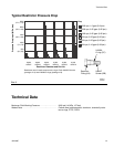
Restrictors create back pressure and make up for vis-
cosity differences between A (ISO) and B (RES). See
pressure drop chart in F
IG. 2 on page 15 and see the
Volume Balancing section. See 249765 Restrictor Kit
on page 14.
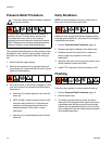
1. Perform Pressure Relief Procedure, page 10.
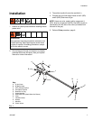
2. Remove restrictors (E).
3. If using one or more restrictors, assemble
o-rings (CC) and screens (BB) onto restrictors (AA).
See F
IG. 2 on page 15.
4. If using one or more plugs (see Accessories on
page 14), assemble o-rings (CC) onto plugs.
5. Screw assembled restrictors or plugs into outlet
manifold (F).
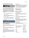
Volume Balancing
Ratio errors can occur between the proportioner and the
manifold, even if the proportioner output ratio is very
accurate.
Different restrictor sizes are available to correct imbal-
ances. See F
IG. 2 on page 15 for available sizes.
Check Valve Imbalance
If resin and hardener are at or near 1:1 ratio, when one
check valve opens, the resulting surge closes the other.
This check valve oscillation causes ratio imbalance.
Install restrictors on both sides to meter a smooth flow to
the manifold.
Sizing Restrictors
If resin and hardener are at or near 1:1 ratio and viscos-
ities are similar, add a few hundred psi pressure drop to
each side to prevent check valve oscillation. Use the
chart in F
IG. 2 on page 15, or use a restrictor about
twice the size of your spray tip, on both sides.
Maintenance
Routine Cleaning
Restrictor Screens
Soak the restrictor screens in solvent regularly to clean.
If soaking is ineffective, replace restrictor screens.
Restrictors
Soak the restrictors in solvent and use the included
vise (30) and drill bit (31) to clean the orifice.
Check Valves
Soak the check valves in solvent. Use a small screw
driver to actuate the check valve ball and spring to
remove any restriction. Ensure fluid flows freely through
the check valve before re-installing.
Outlet Manifold
Use drill bits to clean the outlet manifold (F) regularly.
See the following drill bit size table.
NOTICE
Restrictors and plugs can be damaged if they are
overtightened. Torque to 40-50 in-lb (4.5-5.6 N•m).
Item Drill Bit Size
Outlet manifold fluid outlet . . . . . 1/4 in. (6 mm)
Outlet manifold inner passage . . 1/8 in. (3 mm)
(Restrictor size) 0.018 in. . . . . . . #77 (0.45 mm)
0.024 in. . . . . . . . . . . . . . . . . . . . #73 (0.61 mm);
included
0.032 in. . . . . . . . . . . . . . . . . . . . #67 (0.81 mm)
0.040 in. . . . . . . . . . . . . . . . . . . . #60 (1.01 mm)
0.062 in. . . . . . . . . . . . . . . . . . . . 1/16 in. (1.59 mm)
0.094 in. . . . . . . . . . . . . . . . . . . . 3/32 in. (2.38 mm)
Drill bit pin vise. . . . . . . . . . . . . . 117661; included