


Installation
332198C 7
Installation
1. Relieve all system pressure before installing the dis-
pense valve.
2. Ground the gun through connection to a properly
grounded fluid hose and pump. See your system
manual for further information.
3. Thread the handle (K) onto the manifold (L).
4. Connect the gun fluid supply hoses to the A (ISO)
and B (RES) fluid inlets of gun.
NOTE: Hoses are color coded: red for component A
(ISO), blue for component B (RES). Red (ISO) usually is
connected to the left side of the valve (as viewed from
the back of the gun).
5. Perform Prime procedure, page 8.
GROUNDING
The equipment must be grounded to reduce the risk
of static sparking. Static sparking can cause fumes
to ignite or explode. Grounding provides an escape
wire for the electric current.
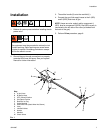
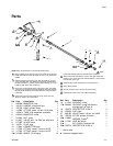
FIG. 1
A
C
D
E
E
B
F
ti20166a
Key:
A A (Iso) Hose
B B (Resin) Hose
C OFF (Closed) Position
D ON (Open) Position
E Restrictor or Plug
F Outlet Manifold
G Static Mixer Nut (Static Mixer Not Shown)
HLever
J Inlet Ball Valves
K Handle
L Manifold
M Check Valves
G
H
J
K
L
M