


Optional Configurations
16 309550U
Optional Configurations
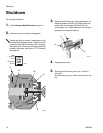
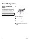
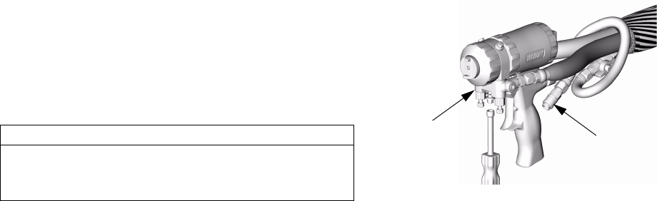
Optional Fluid Manifold
Position
Fluid manifold is mounted to bottom of gun, with A side
on left, viewed from operator’s position at back of gun. If
desired, manifold may be moved to top of gun. Doing
this will reposition A side parts (fluid inlet swivel, check
valve, side seal cartridge, and mix chamber) to right.
CAUTION
To prevent cross-contamination of gun’s wetted parts,
do not interchange A component (isocyanate) and B
component (resin) parts.
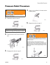
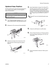
1. Follow Pressure Relief Procedure, page 15.
2. Disconnect air (D) and remove fluid manifold (M).
3. Remove Front End, page 27.
4. Rotate fluid housing 180°.
5. Attach Front End, page 28.
6. Attach fluid manifold. Connect air. Return gun to
service.
TI2554A
M
D