


Maintenance
22 309550U
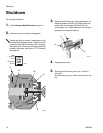
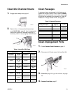
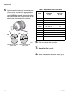
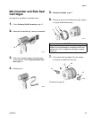
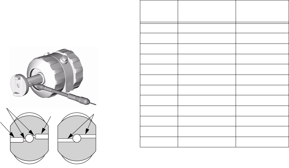
5. Push mix chamber forward until impingement ports
(IP) are visible. See T
ABLE 3 for appropriate size
drill to clean ports. Also see identification chart
under Drill Bit Kits, page 39. Some mix chambers
have counterbored holes (CB) and require two drill
sizes to clean impingement ports completely.
TI2420A
IP
CB
IP
TI3533a
Mix Chambers AR and AF,
2020 and 2929
Mix Chambers AR and AF,
4242 or larger
CB
Table 3: Impingement Port Drill Bit Sizes
Mix Chamber
Part No.
Impingement Port (IP)
Drill Bit Size
in. (mm)
Counterbore (CB)
Drill Bit Size
in. (mm)
AR2020 #76, .020 (0.50) #53, .060 (1.50)
AR2929 #69, .029 (0.70) #53, .060 (1.50)
AR3737 #63, .037 (0.94) N/A
AR4242 #58, .042 (1.00) N/A
AR5252 #55, .052 (1.30) N/A
AR6060 #53, .060 (1.50) N/A
AR7070 #50, .070 (1.75) N/A
AR8686 #44, .086 (2.15) N/A
AF2020 #76, .020 (0.50) #53, .060 (1.50)
AF2929 #69, .029 (0.70) #53, .060 (1.50)
AF4242 #58, .042 (1.00) N/A
AF5252 #55, .052 (1.30) N/A
6. Push mix chamber back in position.
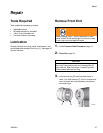
7. Attach Front End, page 28.
8. Attach fluid manifold. Connect air. Return gun to
service.