


Optional Configurations
309550U 17
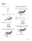
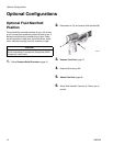
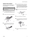
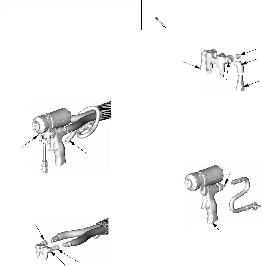
Optional Hose Position
Fluid inlet swivels and air quick disconnect fitting point to
rear. If desired, these positions can be changed so
hoses travel downward.
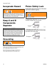
CAUTION
To prevent cross-contamination of gun’s wetted parts,
do not interchange A component (isocyanate) and B
component (resin) parts.
1. Follow Pressure Relief Procedure, page 15. Also
relieve system pressure, see proportioner manual.
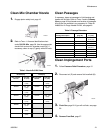
2. Disconnect air (D) and remove fluid manifold (M).
3. Disconnect fluid hoses from inlet swivels (A, B).
Remove swivels. Remove plugs from optional
inlets (P).
TI2554A
M
D
TI2417A
P
A
B
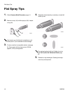
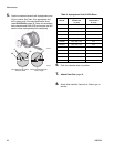
4. Apply thread sealant to plugs (12c), elbows (50*),
and male threads of swivels (A, B). Install elbows
(50*) in optional inlets (P), facing down. Install
swivels (A, B) in elbows. Be sure to install A swivel
(smaller) in A side. Install plugs where swivels had
been. Torque all parts to 235-245 in-lb (26.6-27.7
N•m).
5. Connect A and B hoses to A and B swivels.
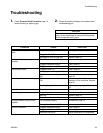
6. Remove fitting (D) and plug (J). Reverse positions.
Apply thread sealant and torque to 125-135 in-lb
(14-15 N•m).
7. Attach fluid manifold. Connect air. Return gun to
service.
TI2646A
50*
B
P
A
12c
Elbows (50*) are not included with spatter spray
gun.
TI2540A
J
D