


Maintenance
309550U 21
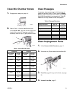
Clean Mix Chamber Nozzle Clean Passages
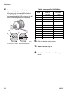
If necessary, clean out passages in fluid housing and
handle with drill bits. Refer to T
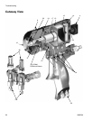
ABLE 2 and to Cutaway
View on page 26 for diameter and location of passages.
All drill bits are available in an accessory kit. Order kit
248969 for Air Purge Handle Drill Kit, see page 40.
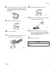
Clean Impingement Ports
1. Engage piston safety lock, page 10.
2. Refer to TABLE 1. Also see identification chart
under Drill Bit Kits, page 39. Use the appropriate
size drill bit to clean mix chamber nozzle (N). If
necessary, clean air cap (C) gently with stiff brush.
Table 1: Nozzle Drill Bit Sizes
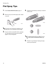
Round Spray Flat Spray
Mix Chamber
Part No.
Drill Size
in. (mm)
Mix Chamber
Part No.
Drill Size
in. (mm)
AR2020 #58, .042
(1.00)
AF2020 3/32, .094
(2.35)
AR2929 #55, .052
(1.30)
AF2929 3/32, .094
(2.35)
AR3737 #55, .052
(1.30)
AR4242 #53, .060
(1.50)
AF4242 3/32, .094
(2.35)
AR5252 #50, .070
(1.75)
AF5252 3/32, .094
(2.35)
AR6060 #44, .086
(2.15)
AR7070 3/32, .094
(2.35)
AR8686 #32, 0.116
(2.90)
TI2409A
N
TI2418A
C
Table 2: Passage Diameters
Passage Description
Ref. Letter
(page 26)
Diameter,
in. (mm)
Optional Air Inlet C 7/16, 1/8
(11.0, 3.1)
Purge Air D 1/8 (3.1)
Piston Air E, F 1/8 (3.1)
Air Exhaust G 11/32, 1/8
(8.7, 3.1)
Air Valve Bore H 9/32 (7.1)
Cleanoff Air Not Shown 3/32 (2.35)
Check Valve Holes Not Shown 3/32 (2.35)
Grease Not Shown 3/32 (2.35)
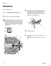
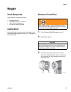
1. Follow Pressure Relief Procedure, page 15.
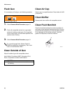
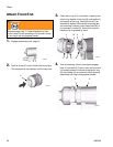
2. Disconnect air (D) and remove fluid manifold (M).
3. Flush Gun, page 20. If gun will not flush, see page
29.
4. Remove Front End, page 27.
TI2554A
M
D