


Spray Tip Selection Chart
32 3A0149E
Spray Tip Selection Chart
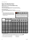
Spray Tips, for use with G15/G40 Air Cap
AAM Fine Finish Spray Tips
Recommended for high finish quality applications at low and medium pressures.
Order desired tip, Part No. AAMxxx, where xxx = 3-digit number from matrix below.
GG4 Industrial Spray Tips
Recommended for high wear applications at high pressures.
Order desired tip, Part No. GG4xxx, where xxx = 3-digit number from matrix below.
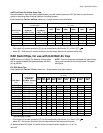
NOTE:
• All tips in the Spray Tip Selection Chart below can
be used with Model G40 guns. Use tips in the gray
shaded area of the chart with Model G40 guns only.
• Do not use tips in the gray shaded area of the chart
with Model G15 guns.
* Tips are tested in water.
† These tip sizes include a 150 mesh tip filter.
‡ Do not use these tips with Model G15 guns.
★ GG4 tips only.
❄ AAM tips only.
Do not use tips in the gray shaded area of the Spray
Tip Selection Chart with Model G15 guns. G15 guns
are not designed for use at high pressures. Failure to
follow this warning can result in serious injury, includ-
ing fluid injection and splashing in the eyes or on the
skin.
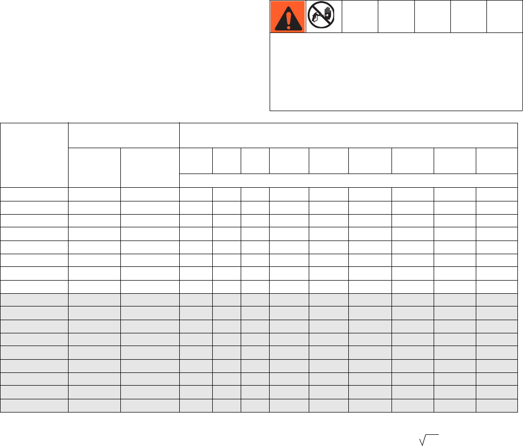
Orifice Size
in. (mm)
* Fluid Output
fl oz/min (lpm)
Maximum Pattern Width at 12 in. (305 mm)
in. (mm)
at 600 psi
(4.1 MPa,
41 bar)
at 1000 psi
(7.0 MPa,
70 bar)
2 to 4
(100)
4 to 6
(150)
6 to 8
(200)
8 to 10
(250)
10 to 12
(300)
12 to 14
(350)
14 to 16
(400)
16 to 18
(450)
18 to 20
(500)
Spray Tip
† 0.007 (0.178) 4.0 (0.1) 5.2 (0.15)
★107 207 307
† 0.009 (0.229) 7.0 (0.2) 9.1 (0.27)
109 209 309 409 509
† 0.011 (0.279) 9.5 (0.28) 12.5 (0.37)
111 211 311 411 511 611 ❄711
0.013 (0.330) 12.0 (0.35) 16.0 (0.47)
213 313 413 513 613 713
0.015 (0.381) 16.0 (0.47) 21.0 (0.62)
215 315 415 515 615 715 815
0.017 (0.432) 20.0 (0.59) 26.5 (0.78)
217 317 417 517 617 717 817 917
0.019 (0.483) 28.0 (0.8) 36.3 (1.09)
219 319 419 519 619 719 819 919
0.021 (0.533) 35.0 (1.0) 45.4 (1.36)
321 421 521 621 721 821 921
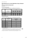
‡ 0.023 (0.584) 40.0 (1.2) 51.9 (1.56)
423 523 623 723 923
‡ 0.025 (0.635) 50.0 (1.5) 64.8 (1.94)
425 625 725 825 ★925
‡ 0.027 (0.686) 58.5 (1.7) 75.8 (2.27)
527 627 827
‡ 0.029 (0.737) 68.0 (1.9) 88.2 (2.65)
629
‡ 0.031 (0.787) 78.0 (2.2) 101.1 (3.03)
431 631
‡ 0.033 (0.838) 88.0 (2.5) 114.1 (3.42)
633 ★833
‡ 0.035 (0.889) 98.0 (2.8) 127.1 (3.81)
435
‡ 0.037 (0.940) 108.0 (3.1) 140.0 (4.20)
737
‡ 0.039 (0.991) 118.0 (3.4) 153.0 (4.59)
539 639 839
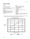
Fluid output (Q) at other pressures (P) can be calculated by this formula: Q = (0.041) (QT)
where QT = fluid output (fl oz/min) at 600 psi from the above table for the selected orifice size.
P