


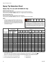
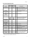
Spray Tip Selection Chart
3A0149E 33
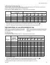
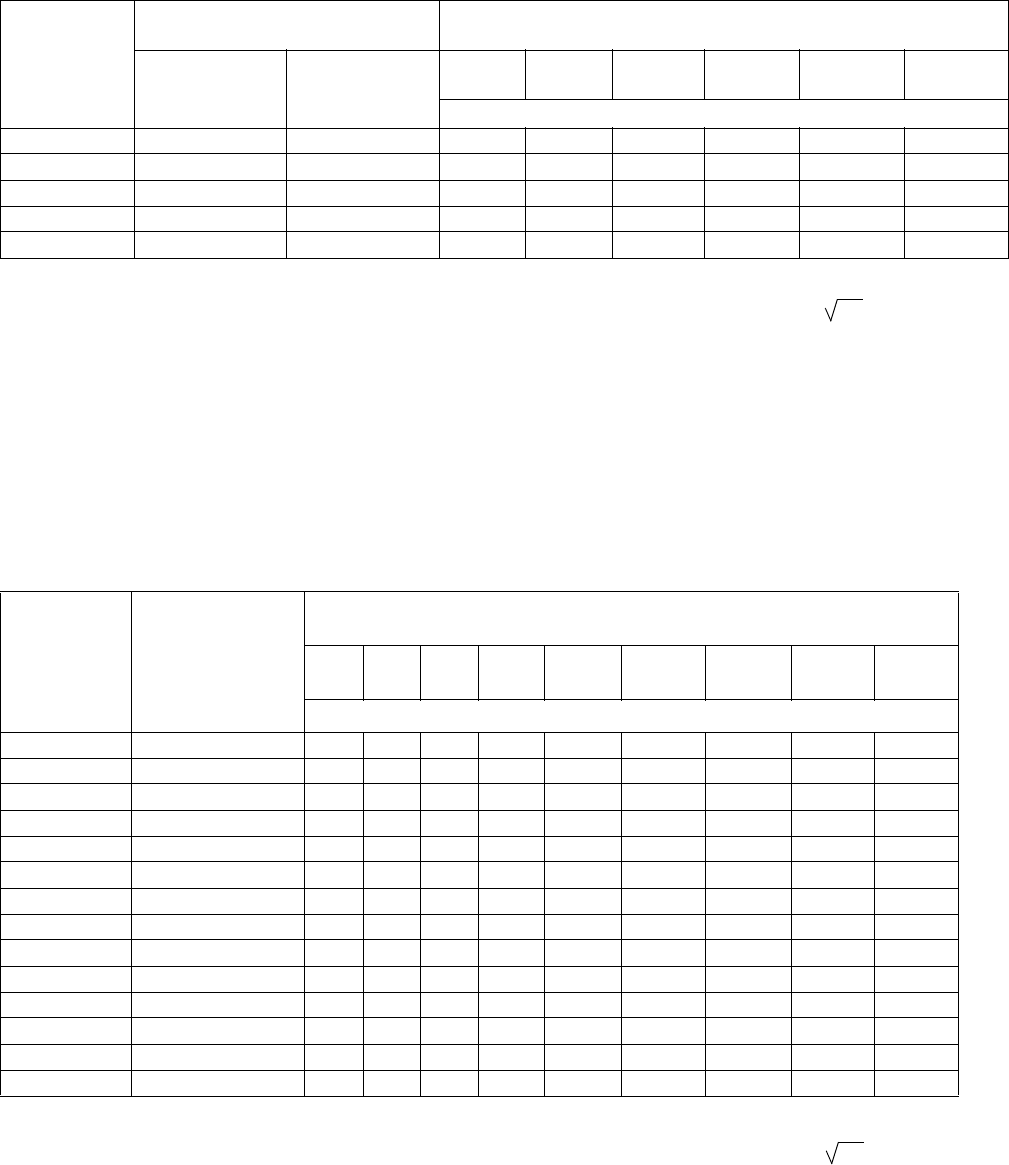
AAF Fine Finish Pre-Orifice Spray Tips
Recommended for high finish quality applications at low and medium pressures. AAF tips have a pre-orifice that
assists in atomizing sheer thinning materials, including lacquers.
Order desired tip, Part No. AAFxxx, where xxx = 3-digit number from matrix below.
* Tips are tested in water.
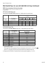
RAC SwitchTips, for use with G40 RAC Air Cap
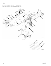
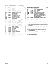
NOTE: All tips in the Spray Tip Selection Charts below
can be used with Model G40 guns equipped with RAC
air cap 24C921.
NOTE: Tips are sometimes packaged with other promo-
tional parts intended for the airless market. Disregard
extra parts.
LTX RAC Spray Tips
Order desired tip, Part No. LTXxxx, where xxx = 3-digit number from matrix below.
* Tips are tested in water.
❖ Measured with NO airflow. Air assist will tend to reduce pattern lengths by 1 in. to 2 in.
Orifice Size
in. (mm)
* Fluid Output
fl oz/min (lpm)
Maximum Pattern Width at 12 in. (305 mm)
in. (mm)
at 600 psi
(4.1 MPa, 41 bar)
at 1000 psi
(7.0 MPa, 70 bar)
4 to 6
(150)
6 to 8
(200)
8 to 10
(250)
10 to 12
(300)
12 to 14
(350)
14 to 16
(400)
Spray Tip
0.009 (0.229) 7.0 (0.21) 8.5 (0.25)
208 308 408
0.011 (0.279) 9.5 (0.28) 12.5 (0.37)
210 310 410 510 610 710
0.013 (0.330) 12.0 (0.35) 16.0 (0.47)
212 312 412 512 612 712
0.015 (0.381) 16.0 (0.47) 21.0 (0.62)
414 514 614 714
0.017 (0.432) 20.0 (0.59) 26.5 (0.78)
416 516 616 716
Fluid output (Q) at other pressures (P) can be calculated by this formula: Q = (0.041) (QT)
where QT = fluid output (fl oz/min) at 600 psi from the above table for the selected orifice size.
P
Orifice Size in.
(mm)
* Fluid Output,
at 2000 psi
(14.0 MPa, 140 bar)
fl oz/min (lpm)
❖ Maximum Pattern Width at 12 in. (305 mm)
in. (mm)
2 to 4
(100)
4 to 6
(150)
6 to 8
(200)
8 to 10
(250)
10 to 12
(300)
12 to 14
(350)
14 to 16
(400)
16 to 18
(450)
18 to 20
(500)
Spray Tip
0.009 (0.229) 11.2 (0.33) 109 209 309 409 509
0.011 (0.279) 16.6 (0.49) 111 211 311 411 511 611
0.013 (0.330) 23.3 (0.69) 213 313 413 513 613
0.015 (0.381) 30.8 (0.91) 115 215 315 415 515 615
0.017 (0.432) 39.5 (1.17) 217 317 417 517 617 817
0.019 (0.483) 49.7 (1.47) 219 319 419 519 619 819
0.021 (0.533) 60.5 (1.79) 221 321 421 521 621 721 821
0.023 (0.584) 72.7 (2.15) 323 423 523 623 723
0.025 (0.635) 85.9 (2.54) 225 325 425 525 625
0.027 (0.686) 100.0 (2.96) 227 327 427 527 627 827
0.029 (0.737) 115.6 (3.42) 329 429 529 629 729
0.031 (0.787) 131.8 (3.90) 231 331 431 531 631 831
0.033 (0.838) 149.4 (4.42) 433 533 633 833
0.035 (0.889) 168.4 (4.98) 235 335 435 535 635 735 835
Fluid output (Q) at other pressures (P) can be calculated by this formula: Q = (0.041) (QT)
where QT = fluid output (fl oz/min) from the above table for the selected orifice size.
P